Blog Entries
- 1/14/2019
- 10/15/2018
- 10/8/2018
- 10/1/2018
- 9/28/2018
- 9/25/2018
- 9/19/2018
- 9/18/2018
- 9/17/2018
- 9/12/2018
- 9/8/2018
- 9/7/2018
- 9/6/2018
- 9/5/2018
- 9/4/2018
- 9/1/2018
- 8/27/2018
- 8/23/2018
- 8/22/2018
- 8/16/2018
- 8/13/2018
- 8/8/2018
- 8/7/2018
- 8/6/2018
- 8/3/2018
- 8/2/2018
- 8/1/2018
- 7/31/2018
- 7/29/2018
- 7/28/2018
- 7/26/2018
- 7/25/2018
- 7/24/2018
- 7/23/2018
- 7/19/2018
- 7/18/2018
- 7/17/2018
- 7/16/2018
- 7/11/2018
- 7/10/2018
- 7/9/2018
- 7/8/2018
- 7/5/2018
- 5/20/2018
- 5/19/2018
- 5/17/2018
- 5/15/2018
- 5/14/2018
- 5/10/2018
- 5/9/2018
- 5/8/2018
- 3/22/2014
- 3/16/2014
- 2/22/2014
- 2/11/2014
- 2/7/2014
- 1/24/2014
- 1/17/2014
- 1/15/2014
- 1/12/2014
- 1/11/2014
- 1/6/2014
- 1/4/2014
- 1/1/2014
- 12/29/2013
- 5/7/2013
- 4/30/2013
- 4/25/2013
- 4/6/2013
- 4/4/2013
- 4/2/2013
- 4/1/2013
- 3/23/2013
- 3/19/2013
- 3/18/2013
- 3/14/2013
- 3/12/2013
- 3/11/2013
- 10/27/2010
- 10/11/2010
- 10/8/2010
- 10/5/2010
- 10/4/2010
- 9/29/2010
- 9/28/2010
- 9/26/2010
- 9/25/2010
- 9/21/2010
- 9/19/2010
- 9/18/2010
- 9/17/2010
- 9/16/2010
- 9/15/2010
- 9/14/2010
- 9/12/2010
- 9/11/2010
- 9/10/2010
- 9/9/2010
- 9/8/2010
- 9/7/2010
- 9/6/2010
- 9/4/2010
- 6/1/2009
- 5/31/2009
- 5/30/2009
- 5/7/2009
- 10/14/2008
- 10/10/2008
- 10/8/2008
- 9/18/2008
- 9/17/2008
- 6/9/2008
- 6/6/2008
- 6/5/2008
- 6/4/2008
- 6/3/2008
- 10/22/2007
- 10/19/2007
- 10/18/2007
This page is a place where I blog about electronics, robotics, and hardware hacking projects that I am working on at the time. Originally it was a robotics only page so the first entries start out talking about that project, but I eventually move away from talking strictly about robotics.
1/14/2019
CircuitPython Projects for 2019
It's been a while since I've been posting a lot on YouTube. I wanted to create a list of Projects that I would like to work on in 2019:
- Getting the Arduino Mega Sensor Shield (currently have Version 2.0 but might get version 2.4) working on an AdaFruit GrandCentral with CircuitPython.
- The above board will host various sensors such as IR sensors, the Ultrasonic Ping Sensor, Light Level, and other similar type sensors.
- I would like to see an RA8875 LCD Panel Driver working in CiurcuitPython.
- Also I would like to see the DS3231 Clock Module working with CircuitPython.
- Another Project I attempted to work on last year included displaying characters on the HalloWing, but found out it is only capable of displaying images, so I would like to see a character library available.
I'm sure I will come up with more projects throughout the year, but these are projects that would be nice to work on in CircuitPython
10/15/2018
I posted another Youtube Video at About unboxing my new camera for making better quality Youtube Videos. I've been working all weekend on the keypad driver for the Hackulator and am making good progress. If you would like more details and more frequent updates, you can check out My Hackaday.io project page. Since I have my Youtube channel going, updates on this blog are going to become much less frequent, so please subscribe to youtube. I may also post updates on twitter.
10/8/2018
Big changes. After having a lot of clarity lately, I have decided to start my Youtube Channel going. I uploaded a video about restoring my Commodore 64 using a beer making enzyme buster which is meant for cleaning beer making supplies. Watch the video to see how well it worked. With all of the projects I have been working on and completing, I figured that this blog isn't really doing them justice and I will be moving to more of a project-oriented video format. While I admit cleaning a Commodore 64 isn't quite as exciting as some of the other projects I've been working on, it actually is pretty interesting to see the Commodore 64 being disassembled. I had recorded the raw footage and had only half edited the video. After resolving to get my Youtube channel going, I went ahead and finished the editing and uploaded it.
I still have some things to set up for the channel such as creating a thumbnail image for the video, but I at least came up with a good name for the channel. I'll be getting a better camera soon and will start recording some of the projects that I've worked on such as my Octo-Power Outlet which I need to disassemble to replace the relay module anyhow. I want to cover my 3D printer and I have a few other surprise projects that I haven't even mentioned on here yet. My plan is for this blog to start wrapping up and posts to become less frequent, so be sure to subscribe to my channel if you would like to keep up to date on my projects. I will probably be moving updates over to twitter as well as it is a convenient place to post quick updates. I have links to my social media channels at the bottom of my website.
10/1/2018
This weekend, I finished writing the battery voltage monitor for the Hackulator. While doing research about how to display the battery voltage in the menu for the Raspberry Pi, I initially came across some information that developing plugins for LXPanel was the way to go. However, it seems the Raspberry Pi PIXEL environment is a highly customized version of LXDE and I was unable to find information of how to create a plugin. However, did notice that there is an existing plugin called "System Tray" which is part of the menu by default, so I looked in that direction and came across some python code that uses GTK+ to display an icon in that system tray. In fact the code I came across was for a battery monitor that read some system information about the battery and showed a representation there.
I was able to adapt this code to work with my existing python code that read the MCP3002 instead of the system and now it's working great. I just need to find the best way to run this on startup and it should be finished. My plan is to take a similar approach for the keypad, except I'll be doing that in C since I'm more comfortable doing low level stuff there. However, if it turns out rewriting my keypad driver in Python is easier, I'll go that route.
I finished installing the camera mounting adapter and put everything back together. Unfortunately, while looking through in different light, I noticed that the camera was set in a little too deeply. I made some adjustments to the design and made the camera inset about half a centimeter less, thickened the plate that it bolts onto, reprinted it, and reinstalled it and it's perfect now.
Another project that I started working on this weekend was hacking an HDMI switch. What I am trying to do is make it so that it can be controlled remotely with OpenHAB and I wrote a quick driver. After uploading it, it wasn't connecting to the MQTT server. I plan on getting it working on a NodeMCU first and then trying again. Basically, I have it connected to the output for the 4 LEDs to get which port is active and the button to trigger it to advance to the next one. My plan is for the software to figure out the current port and just advance it the appropriate number of times to get to the desired port.
9/28/2018
Tonight I went to mount the camera in my adapter and it turns out it was just a bit too big. After a few more revisions, I printed another one out, put some double-sides foam tape so it would have a bit of a seal and tried it again. It went in tight and fits great. I tested it out and the angle looks so much better with a 15-degree tilt. Since it was dark out by the time I finished up and I don't work tomorrow, I decided I'll go ahead finish up taping everything together and putting the trunk back in order then. I may put the STL file for the camera mount up on thingiverse so that other people in the same situation can use it, though I doubt there will be that many of them.
One of the other project I was working on recently is making the blinds in my office motorized with a servo. I installed a kit that I purchased off the internet. Unfortunately it was made for some larger blinds than is standard around here. I was able to get the servo in and I lowered the blinds by 3/4 of an inch and it worked pretty good. Only issue is due to some small gears in the blinds, I wasn't getting the full range. So my solution was to order a 270-degree servo and swap that out. It came today and I replaced it and now it works great. However, due to the extra costs and the fact that it's not smooth, unless I sourced the parts for a bunch of kits myself, it wouldn't be worth it. cost-wise unless I come up with a simple modification to the servo that came with it and even then, it would still be cheaper to source the parts myself.
Also, I set up the Hackulator with a monitor, keyboard, and mouse and will work on the drivers this weekend.
9/25/2018
I was looking into the LCD Controller Board I have. I received it a couple of weeks ago and it basically works and has the connectors for the LCD screen I have, but I didn't read the eBay ad closely enough and apparently the resolutions and screen ratios are programmed into the controller board and the one I bought had a 1280x800 resolution programmed into it so a black bar appeared on the right. This time I ordered from Aliexpress because the stated shipping times looked much faster (12-20 days as opposed to 24-59 days on eBay). I plan to use the board I have for now and will just swap it out when I get the new one. Also, it turns out that I will be getting another LCD that's 1280x800, but I'm not 100% sure it will be compatible as there are some EDID settings from my research that may not quite match up, but I can hope.
I got the Alexa Sample app going on the Raspberry Pi and it works great. I want to hook up a neopixel strip so it can show volume and if it's waiting on me to talk or if the microphone is off. I got a sample app with the neopixel running in python, but I need to get it running in C++. This is more a project I'm working on as time permits.
Now that the nozzle is replaced on my 3D printer, it's working so much better. I went to go print a mega-print, but after 5 hours, I noticed it had half lifted from the print bed. I decided to try a brim on my print to give it more surface area to stick and that did the trick. I was able to complete the power supply holder with socket and switch. I also printed off the camera mount for my car. I cleaned it up, but haven't had a chance to try installing it yet.
I had one of the relays on my OctoPower box go out. Actually, it's probably been defective for a while. Basically it won't turn on if most of the other relays are on, but it will work if it's turned on before the others. I ordered another 8-Relay board and will swap that out. If I have another relay stop functioning correctly, I'll migrate one of the good relays from the current board. Since I was only using 7 of the outlets, I migrated the other devices to working outlets and updated the configuration in OpenHab,
On the hackulator, I did some more research into the battery monitor and it looks like the correct approach is really to write my own LXPanel plugin. So since I am taking that approach for the keypad, I can learn how to do it and use that knowledge twice. I'm not sure if I can do it with python or if I'll have to rewrite the MCP3002 in C++ or if it can be done with either language.
9/19/2018
Tonight I replaced my 3D Printer nozzle with a 0.4mm nozzle instead of the 0.3mm it had on there and the flow is so much better, so now it's back in operation. I also hooked up my Octo-Power Box and got that working through voice commands and I set up my windows computer to remote start up and shut down and enabled voice commands for that too. That one was harder because I could only find one example that was close, but I was able to get it figured out so that voice worked too. I got the LED strip control I built put up and functioning. I had to re-solder the ESP8266 chip because the flux was conducting and needed to be cleaned and I had a couple surface mount resistors that came loose on the strip that I fixed easily.
9/18/2018
I finished up my Octo-Power Box and it works great. I made some more progress on the Hackulator towards getting it all set up and made a few decisions such as looking into creating some LXPanel plugins to deal with the battery level indicator and the Keypad Driver.
9/17/2018
I received a bunch of the items I've been looking forward to and I also started organizing and prioritizing my projects and realized I had around 12 projects in the works of varying sizes. Over the weekend, I finished up the X-10 Controller Project I started last week including finishing touches on the source code, mounting it in a box, and writing up about the project. I also built a Sonoff Dual Power Outlet Box that I was able to load the Tasmota Firmware onto.
I also made some progress on the Hackulator and fixed the wiring. One of the wires had broken off the USB board. I fixed that and then while plugging the USB into the Raspberry Pi, that connector broke. I ended up redoing it with 26 gauge wire instead of 22 gauge, which was much too stiff and everything fit much nicer. I did some work on turning off the LCD screen when powering down, but don't have that working consistently. I came across an article that details how to do it the way I was actually planning on doing it, so I'll have a closer look at that later.
I worked on my Octo-Power Outlet Box with 8 relay controlled outlets and loaded Tasmota onto the NodeMCU and that actually worked pretty great, so I'll probably just stick with Tasmota for that purpose since it's more fully featured than some of the other firmware I've come across. I also worked on the wiring for the box and stripped and tinned all of the wires needed for the power wiring, which was quite a bit. Unfortunately, I cut my thumb pretty badly with a knife in the process, but I'll live. I found a nice case for the relay board, but when I went to 3D print it, I found that my nozzle was jammed and having difficulty extruding. I ordered some items so that I can replace me 0.3mm nozzle with a 0.4mm nozzle which will allow faster prints and less clogging, but also less fine detail. Since I plan to mostly print cases and not so much precision parts, I figured I can live with that trade off. I also need to work on re-leveling my printer bed and can do that while waiting for the parts to come in.
I also had the OLED display in my X-10 controller flake out, so I re-uploaded the firmware to be sure it was functioning and swapped out the display with my last spare, which the whole process only took me about 5-10 minutes to repair.
9/12/2018
Monday, I received my other Light Switch and it installed very easily. After all the playing around with the X-10 devices, I decided to buy a CM15A off eBay or multiple reasons:
- It plugs right into the wall and can plug into the Pine64, so it is not dependent on Wireless
- It should be able to poll for the status of X-10 devices rather than blindly sending commands
- It works on all House Codes, so it isn't limited to only 16 devices, though that wasn't a deal breaker.
- There's already existing software to interface with this device (Mochad) and an existing binding in OpenHab2.
I got an AdaFruit Huzzah Feather because it can make use of a LiPo battery for reliability and wired up a couple harnesses, so the entire thing can be assembled without a breadboard. I should be getting a project box in a couple of days that I'll stick the circuitry into. I polished up the firmware and implemented the new commands so other people can put together a cheap and easy modern FireCracker controller if they happen to have a firecracker laying around or want to buy one to throw it together. However, even though everything says so online, the All Off Command just didn't seem to work. Everything else did. If you're interested, you can get the code from Github. I also wrote a fairly detailed Readme for how to get this up and running with OpenHAB.
It turns out the micro USB port on the Hackulator isn't working right, so I need to look into that, but it should be fairly simple as it's nothing more than a glorified micro usb extension cable. I will work on this soon. I spent all evening working on rewriting the firmware to be much nicer for public eyes, so I ran out of time to work on this tonight. Also, I started a project for this on Hackaday.io and uploaded a few pictures.
Tomorrow and the next day, I should be getting some stuff to build some OpenHAB friendly Smart Outlets to control even more devices. One of the limitation with the X10 devices is they are only designed for ungrounded devices, which can be a bit annoying. Also, I should be getting another smart dimmer switch identical to the last one I got and I plan to open it up and write some custom firmware so that it can work with OpenHAB and not some Chinese controlled server like they are now.
9/8/2018
I preformed the electrical tests for the Hackulator again and they tested good. I also had to shave down the faux connector so that the battery panel laid flat. I also took a sharpie and colored any places that should be black. The calculator is looking really great and it's pretty much just software that I need to work on at this point.
I went ahead and connected the X10 FireCracker to the Wio Link since it is WiFi capable and I thought it would make a great board to control the FireCracker with. My only concern was that the Wio Link/ESP8266 uses 3.3V logic and since the FireCracker has an RF Transmitter, I wasn't sure if it would work properly at that level. According to the Data Sheet for the PIC 12C508A that is used on the FireCracker, it should function at 3.3V. I figured that I should probably set the 2 items fairly close just in case and after that the best thing to do at that point is to try. I went ahead and took apart a DB9 Serial Cable to use the connector on it since the 4 wires in the cable didn't have the proper connections.
I loaded the Arduino Library and after making some adjustments to the library due to the fact that it was written for a much older version of Arduino, it compiled just fine. I uploaded it to the Wio Link and the program worked great. I decided to keep the DB9 Connectors on the FireCracker in case I ever needed to replace that component since they are still available to purchase. This will make it much more modular and less work for me. I received a couple ESP8266 NodeMCU boards today that I had ordered. I hooked up the OLED I had bought for the function generator since I decided not to continue working any further on that project because it was more to scratch an itch than anything else. I attached the Firecracker to the NodeMCU and uploaded the code I had been working on and it worked great. I modified it so that it displays the command that it is sending along with the House Code and Device ID.
After that I spent some time writing some code that subscribes to my MQTT server, which is running on my Pine64 and listens for commands. If it gets a command, it decodes it, sends it to the FireCracker, which is received by the X10 Radio module which transmits it through the house wiring to the rest of the house. There's a lot of optimization that could happen with the Arduino code, but I wanted to write something that at least functioned. Later, I plan on designing and 3D print a simple box for the NodeMCU along with a cutout for the display, a hole for the USB Port, and a place to attach the serial port.
I also got a Smart light switch that I would like to get working with OpenHab. Currently it works with Smart Life, which from my research is really a rebranded Tuya. It looks like several people are trying to get this working, so at least I'm not alone. For now, it at least works with Alexa. As you can probably tell, I like challenges like this and tend to do pretty well with tackling them.
After that, I'll probably design and 3D print a box for the NodeMCU along with a cutout for the display, a hole for the USB Port, and a place to attach the serial port.
9/7/2018
Tonight I almost completely finished assembling the Hackulator. I decided I was going to glue the rear cover on so I could cut more of the insides away because it was so tight. I ended up using hot glue to place things inside and had to make a few minor adjustments such as making wires longer or re-gluing parts in a slightly different place. I had accidentally pulled an SMD LED off with some hot glue and overheated it while trying to solder. I was able to put a different LED on in it's place, but it's red instead of blue. I still need to do some final checks to make sure everything still works electrically, but that will be tomorrow. I want to prepare to present it on Adafruit's Show n' Tell soon and I'm thinking either this week or next.
I discovered that the Wio Link (which I had bought off Kickstarter a couple years ago runs with an ESP8266 and I can program it in Arduino. That makes it so much more useful than I originally thought. I'm thinking about using it for my smart home project. I have 2 Wio Links and a load of sensors, so hopefully it will be useful. I was able to get an OLED LCD and strand of 30 NeoPixels successfully working by uploading sketches with the Arduino IDE. I also have a relay module that I'm pretty sure is just sending an on/off to the port.
I pulled out my X10 stuff because I got to thinking and did a search. It appears that some other people have already interfaced with the X10 FireCracker (the computer Interface), plus it's well documented, so I think that will make it much easier to make use of. I opened a radio receiver unit for X10 that was not responding to a remote. The insides had gotten food in them and corroded. I took some solder, flux, and wick and re-tinned the contacts as well as cleaned it up. After putting it back together it started working great.
9/6/2018
So I worked on the software setup for the Hackulator so that I could perform some hardware testing. I had written a little document that outlined the steps of what I did, so I followed those and installed the battery monitor. When I ran it, I got a reading, but it appeared way off. Upon closer inspection, I had discovered that I soldered the 2 resistors in the wrong places. After swapping those I still wasn't getting a good voltage value. After looking at some data sheets, I discovered there's a few differences with the SPI communications between the MCP3008 and MCP3002. After making some adjustments (different config bits and doesn't require additional clock cycle) to the Python code, I got a fairly accurate reading that was off by just a hair, which works for me. The only big issue is that the program that displays the icon blacks out all of the screen except for the icon itself. I'll have to search for a different solution later, but we have a good circuit.
Next I tested the On button after shutting down the Pi and that was successful as well. After that I compiled my keypad program I wrote in C and pushed every button and it worked great. So that means my board design and soldering job was a success. The next steps are to continue with the assembly, which I've decided to just go with hot glue as that simplifies a lot of things and after that it will just be a matter of getting all of the various software components working.
9/5/2018
Ok, it looks like my Smart Home project Version 2.0 is going to be a big focus here soon. This has really been in the planning for a long time. You might wonder why I say Version 2.0 and that's because back around 1996 or so, I had set up my home with all sorts of X10 devices. Most of them were the Radio Shack Plug n Power devices, but they were really just relabeled. I even had bought a kit from X10 that included a module to connect to my computer's serial port and control them. It was a pretty extensive setup and I had a lot of fun doing it. I still have the majority of those X10 devices stashed away in a box including the computer module.
When I bought my Pine64, I had ordered it off kickstarted with the OpenHab package. This means it came with a Z-Wave module as well as OpenHab installed on an SD card. I was under the impression that I would be able to access some UI on the LCD screen when I ordered it. However, I got the wrong box and the Z-Wave module didn't even fit on the Pine64 in that box. After watching some Youtube videos of somebody who has a setup very similar to what I've had in mind for a while, it gave me some direction.
Tonight I went ahead and got Armbian running on the Pine64 and configured the LCD and Touch. Then I installed OpenHab 2 in the background along with JVM as a dependency. I opened it up in a web browser and maximized it and I think the setup will work beautifully. Also, since I have the LCD box, the Z-Wave module fits inside. I would still like to add a Raspberry Pi to control my 3D Printer, but I will probably just use a real Raspberry Pi for that.
After I get OpenHab completely configured to my liking, I will integrate Alexa and my Apple Watch and other things. Although I was originally planning on hacking the Serial X10 module to control some X10 devices, I hear that it is very inefficient by today's standards and I would probably just be better off replacing wall switches and other things with more modern versions. There's still a chance I may try anyways just for the challenge, but that will be later down the road. The LCD Screen/Raspberry Pi project that I want to work like an echo show will end up being a big part of the controls for this project
I also decided to continue working on the Hackulator tonight and went ahead and soldered everything together. I still need to transfer some files onto the Raspberry Pi Zero W since I was using the Raspberry Pi 3 for Development and set up the Battery Monitoring Program and that will be part of the electrical testing which happens next. That's to ensure all connections are attached properly. Once I confirm that electrical testing is good, then remaining assembly will be done.
9/4/2018
I received my Function Generator today and it works great. I discovered how to use the X-Y Timebase on my Oscilloscope to draw a circle using 2 Sine Wave Inputs. I made some other pretty shapes by adjusting the frequency. One cool thing I would like to try in the future is creating square waves that would initialize something like an LCD.
I also received the AIY Vision Kit and assembled it without a problem. I only had issues when trying to boot it up because it would go to a black screen and freeze. With a quick search, I found the trick was to add over_voltage=4 to the config file directly on the SD card immediately after flashing. After that it booted fine. The piezo buzzer wasn't working until after I ran a distribution upgrade. After that, it worked great.
I also received a MAX1000 FPGA board that I had forgotten to mention. It has some additional LEDs and an accelerometer on board, so I could use that as well. It only cost around $30, so I thought I would get it.
I did some more work area setup and put up a couple more shelves as well as cleared my desk off and placed the oscilloscope and function generator down where I can use them. I also cleared out a bunch of RC helicopter stuff from a parts storage container and I plan on moving all of my semiconductors there so that everything is spread out a little better.
9/1/2018
Well, I still haven't had time to work on my projects, but I should very soon. My wife left this morning to Colorado to help her Mom for a couple of months and the reason I haven't been able to work on my projects is because I was helping with all of the packing. I'm going to PAX tomorrow, so I'll be busy all day, but I should be able to resume projects on Monday.
I took the opportunity to set up my work area a little better today. I still want to mount some shelves and set up another lamp or two, but I have much more desk space. While working on things, I had an idea for another project. It's something I've been thinking about for the past few days after seeing some projects on Youtube. I'm looking at running Alexa off the Raspberry Pi 3 that I have. I have a spare 16" LCD screen that I picked up a while back at Goodwill for $2.50. I ordered an LCD Controller board off eBar for $22.50, so the total cost is only $25 so far. I'm thinking several ideas with how to get it up and running including mounting it on the back of a piece of glass to make a Magic Mirror running Alexa, or I might set it up more like an Echo Show. It will probably take a couple weeks for that to arrive, so I have some time to think about it.
Earlier this week, I was the Adafruit Ask an Engineer Trivia Winner and I talked about my calculator project that I'm pretty close to finishing. I won a Google AIY Vision Kit and I'm hoping to be able to integrate that into the project with the LCD screen. I was really nervous talking to Ladyada because she's been one of my inspiration with getting back into electronics, but I think I did pretty well.
I received the LCD and added it to my function generator project and it worked great. Since this is more of an experimental learning project, I plan to added the interrupt based timing and display a little more stuff on the LCD and will consider it complete at that point.
I have some shipping updates. The function generator that I ordered and I think it will arrive early next week based on where it is now and the holiday coming up on Monday. I received the Playbox for my Pine64 which I had forgotten about and that went together beautifully. I still need to completely reload Armbian on it because of some space constraints when I tried on an 8GB card. This time I have a 32GB card inside.
8/27/2018
It will still be another few days before I can work on my projects again. I ordered a SSD1306 OLED Module for about $8 so that I can display the settings for my function generator on the it. It works at 3.3V, has only 4 pins, and works with U8GLIB which should make adding it quite simple. Plus it's small, so it doesn't hog much room on the breadboard.
8/23/2018
I learned that the Bus Pirate can be used as an AVR programmer, so if I make my own circuit with an AVR then I shouldn't need to buy a separate programmer for it. I updated the firmware on the BP to the latest community version. I also wrote functions for the waves to return a float between -1 and 1 which I can change the amplitude on and it's working great. Triangle wave was a little different than I thought because it is either rising or falling. I now have it providing around 6000 samples of data per cycle, but I think I can squeeze some more out of it if I am able to use an interrupt timer instead of a delay. I used a similar technique when I was developing the robot board that read PWM signals on 6 channels that I needed very tight timing on.
8/22/2018
I haven't had much time to work on my projects this past week and probably won't for at least another 4 days. However, I did end up ordering a reasonably priced Arbitrary Waveform Generator for about $90 that seems to get good reviews on the internet, but it will take up to a month to arrive. So I may still try and build one with locally sourced parts that's reasonably priced.
I ordered and received an Arduino Due because I wanted to play around with the DACs on it. I bought a genuine one and it actually jumped up in price by about $10 just after I bought it. I ordered and received a 12-bit DAC off of Amazon for about $6 to play around with as well. I put together a simple circuit and uploaded a Function Generator Sketch that I found online, but it uses a table of values that are pre-calculated and the resolution is kind of poor. So it doesn't actually use a "function" to "generate" the signal. I'm rewriting the sketch so that it is calculated out. This is more of a proof-of-concept project than anything else and maybe I can produce a real function generator that people can use.
The existing sketch has one potentiometer to adjust the frequency and buttons to select between 4 different waves. Since mine will actually be generated, I'm adding an amplitude potentiometer as well. I ordered some breadboard mounting ones that should arrive in a couple of days along with some more breadboard. Most of my breadboard is old stuff from Radio Shack that has single bus lines along the top and bottom. Price has come way down too, so I got 3 long ones for about $10. I'll probably continue toying around with this small project for the next few days, but I don't expect to be able to do much else.
I also looked into the Dremel project and it definitely looks possible. I found a model on thingiverse to print off a battery casing along with instructions on how to properly trick the Dremel into working with an AC adapter with a resistor, so I have a couple options to try out.
8/16/2018
I attempted to print the part again on my 3D printer, but it was not extruding properly and failed midway into the print. However, I printed off a nice little case for my Bus Pirate. I may end up redoing that one though. It was a bit thin for my taste and I have the OpenSCAD file, so thickening it shouldn't be a problem. Plus it's a relatively simple design.
I had another idea for a project. One of the things that annoys me about my dremel tool is that it takes like an hour to charge the battery and it runs out in about 5-10 minutes. I do like the option of having it be cordless though. So my thoughts were to get a larger capacity battery for it and modify the old battery so that it allows an AC adapter to plug into the end of it and be cordless. I believe I could take apart the battery, remove the cell, and replace the insides with a barrel connector. Another option would be to 3D print something that goes inside. I think there are a lot of possibilities and it would allow me to have the best of both worlds.
My oscilloscope came today. There were a number of options that I know used to come as trial functionality, but since last December they now come pre-enabled. One of the functions that was hackable was the ability to run the oscilloscope at 100MHz instead of 50MHz. I followed the hacking instructions for that one feature and it's now enabled. I also went and calibrated all 4 probes.
Now that I have a working oscilloscope, I've been toying with an idea for a new project. Of course I want to finish my calculator first, but like any good author who always keeps a collection of story ideas, I like to keep a collection of project ideas. Anyways, my idea is to build an affordable arbitrary waveform generator. I'm still learning about how they work and I know the key to them is to use a DAC (Digital to Analog Converter) along with mathematically calculated signals. For instance, Assuming an amplitude of 5 Volts, a DAC could output anything from 0 to 5 Volts depending on the digital value like say 0-255. For a Sine Wave, it could be as simple as a for loop from 0 to 359 degrees with the digital value being something like (int) Sin(X) * 255 with X being the degrees. and a Triangle Wave would be (int) X/360 * 255. and a square wave would be (int) Round(X/360) * 255. I was thinking of exploring something like the Arduino, Raspberry Pi, or Beagle Bone Black to start out with. Also, it may end up being a good FPGA project.
8/13/2018
This weekend I worked some more on my 3D printer with trying to make some larger prints. I updated to the latest version of Marlin and increased some of the printing speeds. I tried out some larger prints, but it seems that 80 degrees celsius wasn't cutting it for the print bed. I was able to get it to 100 now that I have a thermistor right next to the heating plate. Also, the heating plate isn't perfectly flat anymore, so I took out the glass, cleaned it off, put a sheet of Kapton tape on it and clipped it on top of the heating plate, and re-leveled the bed.
After about 6 hours, I successfully printed off the tallest item I've ever printed off, but with a couple problems. First, the bed was just a bit too high and the printer and it hit its ceiling at the top of the print job and some of the layers separated. I increased the temperature of the hot end to deal with the separating layers and tightened the bed leveling screws and re-leveled the bed to deal with the height issue and will give it another try tomorrow. I have a feeling I'll have better luck.
Instead of using my Raspberry Pi 3 for the 3D printer, I decided to use a Pine A64+ that I got off Kickstarter a while back since I already have a nice 7" LCD panel with it. Then I can use it for web-based printing as well as having a nice screen to control the print job. I ordered an injection-molded case for it so that I can have it in the enclosure. When I originally got it, I got a non-LCD case and added the LCD as an afterthought. I went ahead and installed Armbian since it works with the LCD and started setting up the various pieces of software to control the 3D printing including OctoPrint and PrintRun. Unfortunately after spending several hours installing dependencies, I ran out of space on the SD card, so I have to start over with a larger one. :(
I went and ordered a Rigol DS1054Z digital oscilloscope because I had sold my bulky analog one a couple years ago and the cheap oscilloscope kits I put together just didn't seem to cut it and I need this tool to push forward with my inventing.
I received the FPGA in the mail today, but I won't be able to get to that at this time. It will be in one of my upcoming projects.
8/8/2018
The circuit boards came today. I went and soldered the components on the board and spent a bunch of time carving up the insides of the calculator (plastic removal). I still need to figure out where to solder the switch for the PowerBoost and and then it will just be figuring out where to mount stuff. I will probably be using a combination of superglue, hot glue, and possibly making something on the 3D printer.
8/7/2018
Since I now have my 3D printer working, I decided to finish designing the camera adapter for my car. Unfortunately it's getting late, so I will need to wait for another day to actually print it off. It's very possible that I'll need to print it off multiple times while making adjustments in between, but that's the nature of prototyping. Fortunately I made it quite easy to make any adjustments just by changing a few parameters. After I get it all worked out, I may throw it up on Thingiverse in case somebody else with a similar car runs into the same issue.
While I was looking back at some older entries, I realized that I forgot to mention that I did end up replacing the stepper motor for the X-Axis shortly after that post.
Oh, and the circuit boards for the calculator are finished and should arrive her in a couple days. Then I can finish up the hardware part on that project.
8/6/2018
So far it's looking like all the conditions I need to meet to get the voltage checker implemented are coming along nicely. I have the board being fabricated and already have all of the parts in hand. I breadboarded the circuits and they are all functioning nicely and the driver is coming along pretty well.
One thing I'm looking at exploring in the near future is FPGAs because with the price coming down, I feel they are going to start becoming more popular soon. I used to just love designing logic using gates when I was a teenager and in fact created a programmable robotic arm based on an EEPROM to store the data and TTL gates. It probably had about 25 chips on the board including LED display drivers and such. I have disassembled it since then because my skills have improved a lot, but I do still have some pictures of it. I mention this because I may start a project using one if I think of a great use such as building one of my old circuits I designed with many gates, but never got around to making.
I decided to give my 3D printer another try. I started by literally cleaning off the dust and replacing the heated bed screws with some screw knobs I got off Amazon that were much easier to adjust. This had been one of my annoyances with the printer since the beginning. I then leveled the bed, but realized I shouldn't have done it while it was hot because the screws got hot too, so I used some pliers and it was pretty easy.. After that I tried a print, but no luck. After some more time uninstalling software from the computer because it was so slow, I found the culprit to be Synergy. I'm not sure which version it was because I purchased the newer one, but it's possible I never updated it.
I installed Ultimaker Cura and while trying to copy some settings from slic3r, I noticed it was set to 3mm filament which would cause under-extrusion. I flipped it back to 1.75 and gave it another go and this time just a little too much extrusion. I can work with that. I measured and adjusted the extrusion steps in the firmware and tried again and it turned out great. It actually makes me a little teary because I was really getting to the point where I was really feeling limited by not having a working 3D printer and I could tell it was so close to being in my grasp.
On a similar note, it appears an updated version of the marlin firmware was released about a week ago, so I'll have to compare settings when I have a good hour and plug them in and update it.
8/3/2018
Tonight I hooked up the shift register to an LED bar graph and wrote a little demo program and some utility functions in C to animate the LEDs. It turns out WiringPi has a library for the 74HC595 which makes things very easy. After getting this functioning, I don't think there will be any problems with the board design, so I feel pretty good about it. I also wrote some initialization code for the columns. Oh, the only other thing I was considering is writing it in Python, and at this point the only reason I would do that is if I can interact with the Linux UI and display an icon much more easily than with C so I can display if the keypad is in alpha mode or second mode.
8/2/2018
I'm so awful. I revised the design again, so I cancelled my order, uploaded the new design, chose the Super Swift service which takes up to 5 days instead of 12, but doubles the cost. and resubmitted it Also, I went with free shipping because I found they were actually pretty close to where I live and the shipping time would be very fast anyways. It has already gone into production now, so there won't be any more changes, but I'm actually pretty happy with how it ended up. If there turns out to be a major design flaw, at least I know it will only cost me $7.30 and a week of waiting.
On a different note, I discovered that my local library offers free access to Lynda.com and they have a great course on debugging 3D Printer issues and one of the things they mentioned is trying out some different software (many of which I didn't realize was available).. Also, a possibility is that my extruder motor doesn't have enough power and it's under-extruding as a result. That's probably the first thing I'll try the next time I fire up the printer.
Also, another fun project in the future may be to hook up my Raspberry Pi to the 3D printer and install OctoPrint on it and then I can print over the network from other computers. I would want to get it printing much more consistently first though.
8/1/2018
I went ahead and designed a board that is only 1 inch by 3/4 of an inch which I'm pretty sure will be able to fit. By making it so small, I was able to get the cost down to $3.65 for 3 boards and I had the option of free shipping. I opted for priority mail shipping to speed it up by up to 3 days. If anybody is interested in the design, it's available here.
I thought that when I connected the battery backwards to the PowerBoost 1000, I had ruined it so I ordered a new one. It turns out I just didn't wait long enough. Oh well, that can either go towards a different project or a second calculator. It's looking like it may not be until closer to the end of the month that I will have the basics completed. I'll continue working on the software parts of the project. By the time that the circuit board and parts arrive, it should be ready to assemble. Until then, I plan on cutting out a rectangle of circuit board to use as a placeholder.
7/31/2018
Yesterday I didn't get a whole lot done. I mostly worked on some of the driver code and changing it from reading 4 inputs to more of a matrix.
Today I hooked up the MCP3008 and enabled the auxiliary SPI and it's working great. I found some software called GBZBatteryMonitor which is really just a stripped down version of PiCheckVoltage that's a little newer. I updated the MCP3008.py file with the correct pins and it worked well. It turns out when I swapped connectors for the battery, the new connector had the wires opposite of the one that came with the battery. So swapping connectors as well as wires resulted in the battery being connected backwards. I went ahead and fixed that. I also updated the python code that monitors the battery to use the second SPI port as well as making it so I can disable the status LEDs by setting them to 0 since that was a couple GPIOs that I wasn't planning on using.
So it looks like the piece of the puzzle that I thought was most unlikely to work is working. However, since there is a voltage divider going across the battery, my concern was that even with the power off, it will still continue to draw power from the battery, possibly causing it to go too low to charge. However, after doing the calculations, it should only yield a 0.54ma draw which very is negligible. Also, for the main circuit, since it only uses 1 ADC channel, I can get away with a MCP3002 which only has 8 pins. The next piece is to hook up the shift register to the keypad and make it so my driver works with that.
7/29/2018
I ran into another issue with trying to get the MCP3008 chip working. It uses SPI and apparently the Raspberry Pi only has to Chip Selects available for its use on the main SPI. Both of these are in use by the display and touchscreen which are higher priority than a battery level check. Now there is an auxiliary SPI as well, but that would end up taking 4 pins as opposed to the one or two pins I was planning on using because I have to use a different set of MISO, MOSI, and Clock pins as well. In order to do that, this means I will need 4 things to be in place:
- PiCheckVoltage will need to run fine over the auxiliary SPI
- I will need to create a shift register circuit for the keypad
- The circuit that houses both the MCP3008 and 74HC595 (two separate circuits using through-hole chips) will need to be able to fit in the case
- I will need to write a custom driver rather than use a device tree overlay
If any of those 4 things doesn't work, then the voltage check will need to be scrapped. If it's only the circuit fit that's a problem and it's really close, I may be able to design an SMD circuit that fits. Also, I'm not sure if I'll use proto-board or just use OSH Park to make the board even if it fits fine, That's mostly a time vs space issue since I would need to design the board and then it's a 12 day turnaround, so that could easily take 3 weeks total.
I was able to sort of get the device tree overlay working. Some of the buttons responded, but it also seemed to think there was other buttons being pressed. I think I will leave the overlay file as it is for now and start focusing on a custom driver in c because I think I may need more flexibility than the overlay can give me. I am aware that you can do alternate key maps so that if the alpha button we held, then the alpha keys would function and same with the 2nd key. However, I'd rather they work more like the original calculator.
7/28/2018
Ok, so I ended up getting the new calculator in the mail as well as some as the Raspberry Pi 3 B+ yesterday. However, I had a delayed package as well as a couple that were delivered to the apartment office right before it closed, so I had to wait until they opened today to pick them up. So now I also have a circuit board holder, a replacement magnifying glass (like the one I used to examine the circuit board traces), the MCP3008, and a raspberry pi cobbler. I ended up giving my Raspberry Pi 2 to my son because he was excited to get his hands on a Raspberry Pi. Also, I wasn't sure if I would need a power switch, so I got one of those in one of my orders. However, it's looking like it won't be necessary.
I took apart the new calculator and enlarged the window for the LCD using a combination of a Dremel tool, an X-Acto knife, and a file and it turned out pretty good. I hot-glued the LCD in place, kept the keys from my previous TI-83 and started carving up the insides of the calculator for the external ports. I also cut a sheet of Kapton tape to the size of the circuit board that I had from my 3D printer supplies so that I could set boards right on top of the existing board. I wanted to free up an SD Card for my son, so I ended up putting a 16GB card inside the calculator and setting it up just to make sure my process was easily duplicatable. I still need to set up bluetooth again, but I know I can do it for sure now.
I'm considering building a second calculator after my first because a lot of the research and software writing will be done with my first one, so it will be much easier. Besides, I already have much of the stuff needed to set up a second one. I would need a couple of displays, a PowerBoost 1000C, another battery, an HDMI extender, and another USB port (unless I just use that extra one I have). I guess I didn't realize how much stuff I actually needed, but I'll have to think about it.
Since I don't want to solder a header onto my Raspberry Pi Zero, I went ahead and attached the cobbler to the Raspberry Pi 3 and hooked that into a breadboard. I put a little solder on each of the keypad wires and attached them into the breadboard. I went and wrote a good chunk of a device tree overlay file and compiled it, but unfortunately it didn't actually function on my first attempt. I unhooked it and manually tested every key with a multimeter and it tested fine, so I'm not quite sure of the issue yet. Most likely it's something in the device tree file that's backwards or missing. I noticed some artifacts on boot up if I have the keypad connected. Tomorrow, I'll get a T-cobbler and then I won't need to route the wires around the ribbon cable, so that will be nice. Also, as a test, I hooked up the On button and wrote a script to shut it off if I hold the button for 2 seconds and that works beautifully.
7/26/2018
Today I got Bluetooth audio working. I just followed this guide and aside from a misspelling or two, it went pretty smoothly. I wasn't able to get it to play over command line using SSH, but it did play after I installed VLC and double-clicked the MP3 file, which is good enough for me.
A while back, I had discovered that you could download Lynda.com videos with youtube-dl, which placed stuff unsorted. I created an AppleScript script that would go the the Lynda website, get the list of files in the course and sort and rename all of the files accordingly. Over time, I got it working 100% perfectly. It was quite elegant in that it used jQuery that was loaded as part of their webpage to do a log of the heavy lifting. Also, I set a folder label to a color based on the course difficulty. I ended up downloading a bunch of courses from a trial.
So I went to load some files into VLC and it was sorting them wrong and I realized a playlist was just what I needed. Just for fun, I decided to write another AppleScript that recursively goes through each folder and checks if that label is set to determine if it's a course folder or a sorting folder. I could have also checked the name as well since they are prefixed, but this worked fine. So if it was a course folder, it would create an M3U file and sort the list by a numeric index that I prefixed to each file and folder. The hardest part was coming up with a way where 2 was sorted before 10 and so on. There were other scripts out there that created M3U files, but as far as I could find, mine was the only one to include the running time of each video file. Anyways, I finished the script and it worked beautifully. The next step would be to integrate it into the main sorting script, which would be much easier than the way I just did it.
Hopefully I'll do a bunch more calculator stuff tomorrow since that's when a bunch of parts orders are coming.
7/25/2018
Don't you just love breakthroughs? I was looking at the Network mapping data I had and swapped some columns and realized that it is in fact a grid of 7x8 (at least electrically) plus the on button. It's just not arranged physically in the same grid that it is electrically, but it still the same. That means I have the option of using the GPIO-Matrix Device Tree Overlay like I originally wanted.
I received the second USB port and have decided to go with the Adafruit one. The contacts are better and I think the shape works better, but in all honesty, I think either would have worked out just fine.
One of the things I realized is there isn't a good way to check the battery level with my current design. I found a project that allows you to check this, so I ordered an MCP3008 A/D converter that I'll see if I can connect into my project. It really depends on whether I will have room in the calculator case.
I looked at the spreadsheet once again and with removing the audio board, it looks like I'll now have just enough pins because I was planning on using one for either the low battery output from the PowerBoost or the MCP3008 chip. In the event I don't have enough pins for my needs, I happen to have a 74HV595 shift register that I could hook up for checking the keypad that would free up 4 or 5 pins depending on how I decide to connect it. Space is the main issue and I don't believe I'll need to use it since the MCP3008 communicates via SPI and I only need 1 extra pin for the Chip Select. My main concern on that is the Display uses SPI and I don't want there to be any conflict and that will require further investigation.
7/24/2018
I found a great page here about how to write something in C that would be a great base point. If I run it in the background as a service or a daemon just like FBCP, then I think that will work fine. I'm also thinking about reading in a config file or something so that I can make the keyboard function different depending on the mode. I went ahead and set up SSH and got it to compile an example so that I can modify it from there.
I'm kind of getting anxious to put everything in the calculator case soon as I feel the hardware part of this project is coming to a finale and then it will just be software. Part of the reason is because I've already had a couple wires break on me from moving it around too much. I just reattached them, but I'd rather just have everything in the case. With the way I am going to set this up, unless I need to remove the SD card to burn a new image, there's no good reason to open up the case. I'm thinking I should be able to finish the base part of the project up by mid-August and then I can add emulators, expand the keypad driver, play with power options, and set up the environment to exactly how I want it.
I received one of the USB ports today and after playing around with some different possibilities, I think I will end up placing the HDMI port at the top and the USB port on the bottom. Once I get the new case, I will be removing less of the plastic innards, so that some of the plastic I shaved away will be able to support the ports better.
One other quick thing I came across and tested is that Pin 5 works as a wake button which is great news. There's nothing to add to that and I can make off behave by turning off the LCD and shutting down or perhaps I can make the LCD contrast off work so that if it's powered off in the menu.
7/23/2018
I was out of town for most of the weekend, so I wasn't able to get much done. I worked on getting bluetooth audio working and so far that has been a bit of a challenge, but still appears to be within the realm of possibility. On the presumption that I'll get it working, I have been looking at some alternate layouts inside the calculator. Because of leaving out the audio board, I decided that I could probably now fit a USB port that will go directly to the raspberry pi onto the calculator, but I haven't decided if the HDMI port will be where the audio port was or if that's where I'll place the USB port. I went ahead and ordered a couple of micro usb breakout boards to use for the port that are slightly different sizes because I'm not sure which will end up working best.
There was an adhesive on the board from where the LCD ribbon cable was attached. I didn't have any Goo-Gone, so after looking through what I did have, I ended up using some acetone since the only think I know it to dissolve is ABS and just to be sure it didn't have any ill-effects on the circuit board, I tested it on the TI-86 board and it was fine. By the way, I do know that one thing you don't want to use on circuit boards is ammonia because it will dissolve the green solder mask on many boards. Anyways, I tried in on the TI-83 board and it removed the adhesive just like I hoped. It also cleaned the board really well and it looks great.
Next, I finished mapping out the wires to all of the solder points where I was attaching wires into vias. I ended up taking a 25-pin computer cable and using wire from that so that it would all be consistent gauge, yet different colors. It took me about an hour to solder all the wires in place while taking care to not have any solder gaps. I placed all of the calculator keys back into their appropriate places (they had fallen out previously and I put them into a ziplock) and screwed the circuit board back on.
The next steps will be to solder all of the other wires to the Raspberry Pi and then to star writing some kind of driver for it. Hopefully it will end up being easier than it seems, but I'll see. I think I came across something I can use as a starting point and then I'll flesh it all out. Also, I need to test that there were no shorts in the soldering job and I'll do that shortly before soldering the wires to the Raspberry Pi. Another small issue I need to contend with is all of the wires ended up right below where I was planning on putting the Raspberry Pi. That may not end up being a big deal though.
7/19/2018
This is just a short blog entry as I didn't have much time to work on my research. I now have the display working 100%. I got a little impatient and started digging in a little deeper myself. In the end I added spi_bcm2835 into /etc/modules to force SPI to start first and that fixed the issue. I posted my fix on the adafruit github for that issue, so hopefully that will help some other people out.
Another thing I realized that would make some more pins available is that I could just use Bluetooth Headphones. Then I could have my adjustable backlight pin back. I went ahead and ordered a broken TI-83 off eBay for $8 including shipping so that I won’t have the hole that I made for the audio port anymore.
7/18/2018
I went ahead and mapped out the circuit board today. It wasn't exactly the rows and columns that I was hoping for, but rather networks of circuitry. I counted 15 distinct networks plus the on button was separate. When I mapped them out in a spreadsheet, the bottom 8 rows are definitely in a matrix as expected. However, for the top 2 rows and the arrow keys, they use some of the row networks as columns and that's why I decided to map it out as networks (a term I took from Eagle regarding a series of connections all electrically attached) rather than rows and columns.
So what does this mean? Probably that I will have to come up with my own solution for scanning all of the keys. The problem is that some of the pins will need to switch between being inputs to outputs and vice versa which I don't think will be a problem on the Raspberry Pi. Also, I've never written a driver before and not for linux and this is the first intensive thing I've done with the Raspberry Pi. However, I knew going in that this would probably be the hardest piece. and this is kind of what I was initially expecting to do.
So, this means I will need 16 GPIO pins for the keypad, which I think I can manage if I don't use the backlight. I measured the resistance of the buttons to be no more than 100 ohms and with the way the contact is, it will be probably closer to about 25 ohms. The next step will be researching what is involved in coming up with a software solution to scan the keys and are there any limitation that I should look out for. Also, I may need to come up with some kind of serial shifter or multiplexer circuitry so that I don't need to use as many pins if that's even possible with the way this thing is laid out.
7/17/2018
I feel like I'm very close. To start out, I found an alternative FBCP driver for the hardware combination I'm attempting to get working available at https://github.com/juj/fbcp-ili9341. I went through the initial build procedure and it seems to be working with a few exceptions:
- It is displaying a bunch of numbers on the screen which should help with tuning it
- The touchscreen isn't working and this may be a deal killer/li>
- It appears to be choppy, but I need to go through the fine tuning process
After looking in the documentation, it explicitly says touchscreen will not work, but one may be able to get it working if they took a stab at it. After that, I switched back to the Adafruit FBCP. I found that if I run FBCP at the command line after booting it, it seems to work just fine with touch and everything. I tried placing it in the /etc/rc.local file, and it worked for a second, but then another copy started up and it stopped working. After running grep to search for fbcp, I found a service used to start it up. When I type sudo systemctl restart fbcp, it starts right up. I looked to see if anybody else was having the same issue and I found an open issue here which describes my symptoms perfectly. Just after posting a comment on it, it was assigned to somebody to fix, so I'm hopeful that all I need to do is wait for that.
Now as for the keyboard., I found an article that describes how this can be accomplished with setting up a GPIO Matrix Device Tree Overlay and a couple other components. I also came across a couple things that briefly mentioned using diodes to make it so key presses can't be mis-detected. I'll have to do some research on that.
I started mapping out the circuit board for the keypad by taking a picture and importing it into photoshop, but unfortunately I ran into an issue. The circuit board from the TI-86 is so corroded that some of the traces are completely dissolved. That's on top of the complexities of it that it isn't in a perfect matrix. At this point I have the option of repairing the board which would mean some ugly Frankenstein wires and probably having reliability issues down the road or sacrificing the TI-83 that originally came out of the case...with the screen lines that take 10 seconds to reappear...and the now missing battery panel...yeah, I think I'll be sacrificing the TI-83. I know that board is in pristine condition.
7/16/2018
I ended up getting my order of parts for my calculator, which I'm thinking of calling a Hackulator. One of the things I ordered was a mini HDMI port extender so I can hook it up to a monitor without taking apart the calculator and without having all of the ports exposed (though it is still an option at this point). I took all of the boards and the battery and I was able to fit them inside the case. After a little bit of moving items around inside, I'm pretty sure I know where I want all of the boards. For the new display board, I am able to fit it right behind the LCD display, so the extension cable is no longer necessary. Also, it feels like it weighs just a little less than a real TI calculator with batteries.
I looked at the new display board and made note of all of the pins it uses in a spreadsheet and then I did the same for the audio board I got. It turns out that the audio board and the backlight want to use the same pin, so I cut a little trace that's meant to be cut on the display board. I still have the option of using a different PWM pin (GPIO13) if I want to resolder the and hook it up to a different wire. That would leave 15 free GPIO pins if I still use GPIO13 for PWM. The calculator keyboard has 50 keys arranged approximately in a 5x10 fashion so that works out.
The only thing I'm not sure about yet is that for my power board I may need to use an additional GPIO for power control which means no backlight control. Another option is to multiplex the keyboard so that I can send voltage using only 3 GPIOs for the columns instead of 5 freeing up a pin. The downside is that it would require additional circuitry and I don't have much space inside the case.
I already modified the new display board. I successfully desoldered the 2x13 connector from the board and placed electrical tape over that spot so there wouldn't be any accidental shorts. I started modifying the case as well and was able to fit the audio connector right next to the display, which ended up being a bit of a challenge. I still need to enlarge the display window and cut out the HDMI port on the bottom. Once everything is done, if it turns out like I plan, there shouldn't be any issues placing the slide cover on the calculator.
I went and soldered the wires running from the raspberry pi to the new display and at first it wasn't working and I realized it used a split ground plane, so I soldered a second ground wire for the other half. I'm still having an issue where it only works sometimes. I think I have narrowed it down to FBCP because even if it starts up and it's not displaying what's on screen, I'm able to run some programs that output to it just fine. Also the touchscreen is working fine too.
The next step is to continue modifying the case so that everything fits inside. At the same time I need to get the new display board working consistently. I looked and it appears somebody has already written a driver for making use of a matrix keypad, so that should make this that much easier. My goal is to have this completely working by the time I go to the hackaday convention so I can bring it with me. In all likelihood, I think I could get this finished in the next month so that shouldn't be a problem.
7/11/2018
It's worked! Once. I checked all of the connections and everything seemed to checkout fine. I booted it up and it did the same thing as it did yesterday with the black screen. So I figured it wouldn't hurt to try running the script again. It must need to probe something for the settings or my messing around with it may have messed something up, but it started working. As luck would have it, the very stiff HDMI cable I was using lifted the entire setup into the air and the LCD panel fell off. I attached it back on, but I still haven't been able to get it working. I switched to a regular HDMI cable, but I've only been able to get the top quarter inch of the display to work. I'm looking into an alternate solution. I have a resistive display that is exhibiting the same symptoms when plugged in so I think it's the board I'm having issues with.
While it was working with the touchscreen and all, I noticed that attempting to use a capacitive screen did not allow me to click on small things. I'm thinking about switching to a resistive LCD and possibly having the arrow keys control the cursor. I placed an order for an Adafruit PiTFT 2.4" HAT Mini Kit - 320x240 TFT Touchscreen. The advantages to this are that I believe it will work with an existing Resistive Touch LCD that I already have, that it doesn't come with buttons or headers soldered on so there won't be anything to destroy, and because it's designed for a smaller LCD, it's already a smaller sized board.
The next steps are to try booting it with the extension cable, but I don't think that will be an issue and then starting work on making the calculator keyboard working. I'm thinking I'll read them as some kind of matrix and since the buttons have a resistive value, I'm thinking I'll check the resistance to make sure it's not routing a button press through 3 buttons.
7/10/2018
I didn't have much time to work on it today, but I did discover one of the wires I used for repairing was attached to the wrong point. I moved it to the correct place and although the screen did initialize (changed from white to black), it didn't display properly. I still need to check that the connections are proper and that there aren't any other shorts in my soldering job. If that checks out, I can try running the init script for the display, but I don't suspect that will do anything. It could be a similar issue as well on another wire.
7/9/2018
I am so close now with getting the LCD working with the Pi Zero. I got the desoldering tools in the mail, so I went ahead and desoldered the parts I wanted and cut the board down. Unfortunately while doing so, I broke off a few pads. So the next step was looking at a schematic and figuring out which connections needed to be connected between the Pi and the LCD. I meticulously added wire and did repairs on it and tested each with a multimeter and then soldered wire between the Pi and the LCD.
I then went ahead and downloaded a more recent version of Raspbian and installed it on an SD card, hooked the Pi up to my TV and finished the install. I ran a script from Adafruit to set up displaying the output to the LCD and rebooted. It was black. I realized I forgot a ground wire and added that, but still no connection. I removed the LCD extension cable and plugged the LCD directly in the board and it was white. I fiddled with the extension cable and finally got everything the correct side so now the LCD is displaying white. I booted up again and it goes from white to black (but still illuminated) during the process, so that's where I'm at. I also double checked all connections from the raspberry pi to connection points on the board and everything checked out fine and the touchscreen moves the mouse, so it's definitely only the display portion not working.
On another note, it was announced that the Hackaday Super Conference tickets, so I went ahead and snagged an early bird ticket since hardware hacking is one of my favorite activities. Speaking of which, I think I'm going to change the name of this section due to it being more generalized. Probably electronics or maybe hardware hacking or something else if I think of something better. Robotics was just a little too narrow.
7/8/2018
I have made a bunch of progress. First I'll start with the calculator project. I received the PowerBoost and the battery in the mail, so that allows me to know how well stuff will fit. I started desoldering the connections on the LCD board, but that was soldered way too well, so I ordered a solder sucker and that should help with removing the main connector. I then took the insides of the TI-83 and placed them into the TI-86 case which was kind of a fun project in itself. It involved a little cutting, drilling, and soldering, but in the end it functions well. The only thing is that the labels on the buttons don't match up to the actual functionality of the buttons.
I then took the TI-83 Plus case and removed a lot of the excess plastic so I could fit everything inside. I realized there's no audio jack on the raspberry pi zero, but building a small circuit should be doable. I also need to figure out exactly how I want the power on/off to work with the raspberry pi since it will be in a calculator form. Ideally I would like the ON button for the calculator to take it out of a halt state and for it to put it in a halt state if pushed when the shift key is pressed so it functions like the calculator on/off button.
On a different project, I had previously assembled a DSO038 Oscilloscope kit and wasn't able to get it to function properly. Apparently I had missed a step and didn't remove a wire that wasn't supposed to be in there. Removing it restored the functionality, so now I have another completed project as well as another tool.
7/5/2018
Well, for now I'm giving up on my 3D printer and moving onto a new project. After the new project is finished, I may circle back to the 3D printer. The new project involves putting a Raspberry Pi Zero W and LCD into a TI Calculator case and getting the buttons to function as a keyboard. I will also be adding a Lithium Ion battery so that the whole thing is rechargeable.
This is something I've had on the back shelf since December or so when I got the idea. In the mean time I've acquired a couple of TI calculators and the Raspberry Pi Zero W. I also got an extension cable and have been planning how everything will fit in the case. Yesterday I took apart a TI-86 that was non-functional and used a heat fun to remove all of the components from the board. I plan on using a TI-83 Plus for the case because I think it looks a little better and it doesn't have the clear plastic that would go on top of the LCD so I could still use the touchscreen. I'm considering the option of mounting the LCD flush so that it's easier to touch the edges, but I'm not set on that..
I went ahead and ordered a Adafruit PowerBoost 1000 Charger to handle the charging of the battery as well as a battery that should fit where the AAA batteries go. Once I have that, I should have everything I need to complete the project. The next steps are to clean up any remaining solder on the circuit board from the calculator and start mapping out the key matrix.. I'm using an Adafruit PiTFT Plus Capacitive Touchscreen and separating the LCD from the circuit board. The reason for the separation is that the circuit board makes it too big to fit in the calculator case. I may also end up cutting the board down as well as desoldering the buttons and larger connector and soldering the raspberry pi directly to that board. I may also end up soldering a ribbon cable between the board if that would make them too thick. I'm also hoping to be able to fit the PowerBoost where the button cell battery would normally go, but I'll know more once I receive everything,
At this point I need to get everything working together electrically, then I'll get it to fit in the case and finally I also need to work on the software. I'm hoping to find some information about reading the keys and placing the key presses directly into the input stream.
5/20/2018
Today I went and tried out a few new settings. I changed the numbers so that the dimensions were a lot more accurate. Then I went and even though the extrusion rate was too much, I increased it further because it didn't seem like it was flowing together nicely. For another cube, I increased the printing temperature and it seemed to bond together better. I have a suspicion that it's reading the temperature wrong and so I may need to further increase the temp. Regarding the motor slipping on the X-Axis, I realized that was one of the motors I had not upgraded yet, so that may be one of the things I do soon so I can avoid any more layer shifting, especially since I already have the motor.
5/19/2018
I started working on a Bill of Materials. The problem I was finding with the I3 was there were quite a few variations. I believe I have narrowed it down to the MK2S version and I need to come up with a BOM for that. I selected that one because it seems to be a good balance between ease of parts acquisition and sturdiness/features of the printer.
In regards to my current printer, I remembered something about removing a diode if you wanted to power it externally, so I did a little digging. There's a diode on the RAMPS board that if removed, requires the printer to be plugged into a computer. However, the advantage is that the USB power and the main printer power are separated. I decided to go with this since I was pretty paranoid after having the printer blow up the USB port, keyboard, and trackpad of a laptop I had used. While attempting to remove it, it seems I accidentally loosened a capacitor, so I went and pulled out a spare RAMPS board and successfully removed the diode on that.
I went ahead and plugged in the board into the printer and hooked up the wires for the hot end and heated bed and placed the first stepper motor driver into it. Then I played around with plugging various motors in until I had the first axis working correctly. I continued doing this for the other axises and extruder. Then I got the end stops plugged in and finally the temperature sensors. Each time I unplugged the printer between installing stepper motor drivers or plugging in motors so I wouldn't damage anything. I was able to get all of the functions working correctly. I went ahead and adjusted the power screws on the stepper motor drivers. While doing that, I noticed something strange. While I touched a screwdriver to the screw, if the motor was attempting to move, it would play some foreign radio station through the motor.
After everything was set up, I loaded Slic3r and entered my printer settings and decided to print a cube for testing out the dimensions. It went terribly wrong. The infill wasn't printing very good. I slowed the printing down for the inside and increased the heat. I then tried again and it was a bit better, but failed mid-print because it shifted over a few millimeters. I increased the power to the X-Axis since that was the axis it slipped on. I still have a few more things I want to try such as different filament and slowing down the speed. If that doesn't work, I may try a one of my newer how ends. It appears I can take the bowden tube holder out and it should fit right in. However, it's a little taller, so I would have less print area height-wise.
I want to make sure I can print off the printer parts for the I3 before I spend any money on the hardware, so this will be my focus. I'm quite certain I can do it if I adjust enough things.
5/17/2018
So I went to check if I had the latest firmware and I see they now have documented the process of setting of the configuration. So I downloaded the firmware, went through step by step and finished the settings. I was able to get it to compile and upload it to the 3D printer.
One thing I realized is that with all of the extra parts I have, I don't think it would be a huge cost to build and convert it to a Reprap i3 printer. I already have an extra set of smooth rods for the i2, which are longer than I need them to be, so it would just be a matter of cutting them down. Once I get the printer working as it is, I can print off a set of the 3D parts for the i3 and I think I would mostly need some m10 threaded rod ($25 pre-cut, possibly cheaper if I do it myself) and a frame ($20) for acrylic. I think I may need to get an aluminum tray as well, which may cost a bit more. It's also possible that I can get all of the components together as a bundle from Aliexpress for a decent price, though it may take weeks to ship.
The main advantages to switching to the i3 are that it's more stable and has a bigger print area. It looks like my plan to change out the extruder and convert to a bowden style works well with the i3.I think the next step will be coming up with a bill of materials and crossing off what I already have.
5/15/2018
Some of the stuff I have planned (and purchased already) as upgrades for my 3D printer include dual Bowden extruders. I went with the Bowden style to reduce the size and weight of the one of the fastest moving parts of the 3D printer. The momentum caused by the old extruder would literally shake the printer as it went back and forth. Another upgrade is a full aluminum heating plate for better heat distribution as well as a sheet of Kapton tape over the bed so that the item will be removable. I removed the borosilicate (pyrex) sheet of glass because when I've printed directly on it in the past, I've had the print stick so much to it that it literally took a chunk of glass when I removed it.
I went ahead and ordered an extra set of stepper motor drivers, though I may have barely enough on hand to get it working if I mix-n-match. I plan on spending some time working on the printer tonight to see what I can get working. I didn't have much time last night because my daughter had a choir concert that I attended and she did great.
I realized the most time consuming part of getting it up and running will be getting all of the settings for the firmware in place. I had an older version of the firmware and there are new options and some of the other options are now gone, so I just need to comb through everything. I had spent a little time a couple months ago at least downloading the firmware and most of the software to compile it and started plugging in some settings, but I know I have a bunch to do still.
I don't expect this week to be quite as productive as last week due to a couple of things. For one, I made a bunch of social commitments and secondly, I can't do much work on my printer at lunch time like I could on my car. I do have a show that I'm trying to finish up watching and I have about 10 more episodes. After that, I should be much more productive.
5/14/2018
After looking at a few charts, I believe the CAN inputs are for M-CAN (though I did see a couple of sources say C-CAN so I'm not 100% certain), which is the Multimedia CAN channel that the car interfaces with the AVN (Audio/Video/Nav) unit. The next step would be to find where the wires go to it.
At lunch on Friday, I swapped the data lines for the USB port and tested them only to discover that swapping them reversed them. So I looked at some more diagrams and it appears that the one I pulled up off the internet the day before was wrong and that I had originally been correct in the color coding. So that was a wasted 20 minutes plus it'll be another 20 minutes to redo the wire swap. I guess I'm starting to learn now to test and then make the change and test again instead of change then test. So, that means I tested a bunch with everything in the correct position and the video from the camera looked pretty messed up while the USB port was connected to the radio. All I can really do is exchange the wires and try again. It looks like I may have to swap them on the adapter as well.
On Saturday, I swapped the adapter data wires and the wires in the car. I hooked everything up and just before putting it back together, I decided to test if we were getting voltage from the USB port to test with. It turns out that the pinout is reversed from what the diagram shows, meaning all I needed to do was turn the plug around and it worked fine. I also tested the Aux Port and that worked fine. So after going through all of that, I decided that rather than mess with the CAN bus for now, I would rather just have everything back together and so I went to assemble everything. It turns out there were a couple of posts on the back of the panel that goes over the stereo that were lined up for the old stereo and not the new one. I went ahead and shaved those down flat and was able to get everything together. I put the trunk back together as well.
So for my next project, I decided to start working on the 3D design of the camera adapter using OpenSCAD. This is the part I will print off on my 3D printer that will allow me to mount a camera at an angle. I got about as far as making the plate that will go against the car and the housing that the camera will sit inside. I still need to figure out some tabs for holding it into the car as well as take a few additional measurements. I ordered the stepper motor drivers since the ones that I have all seem to have bent pins or missing heatsinks and I think that's all I will need to get my 3D printer working.
5/10/2018
I had an idea for adjusting the camera angle. I could probably make a wedge of some sort if I get my 3D printer up and running. Originally I was thinking of buying a block of plastic and cutting it to shape, but after thinking about it, I can produce exactly what I want if I get the printer up and running. It's a great motivation to work on it and simple enough that there is a relatively high chance of success. Plus I already have the correct filament in black. I would probably need to make a reverse wedge to go on the inside as well. The main potential problem I see here is that it may require too much depth for the length of the screw.
The other option I am considering is getting a different camera with a compatible plug that has a better angle. I found an aftermarket one for a Hyundai Elantra that I believe would fit in the same size of hole, but that would be an extra $25. According to Amazon, it has an tilt angle of 42 degrees from being straight out. I took a picture of my current camera and used a protractor app to approximate the angle and it appears to be around 50 degrees, so that would be a marked improvement.
A great idea I just had is that I could design something on the 3D printer that replaces the plate that snaps into the vehicle with something that puts the camera at exactly the right angle. with the camera sunk in a bit. This may take a bit of time to design, but it would probably be the most ideal result for the cost.
So laying out those options, I think trying to get my 3D printer functioning would probably be the first thing to try. If I can get it going, I may try my hand at designing something that will work exactly right. If that fails, I may try and just print some simple wedges. If that fails, then I'll go with the $25 camera. As an absolute last resort, I could get a camera that mounts above the license plate, but honestly I think I would prefer to stay with what I have now over that option.
I decided to do a comparison and found a pinout diagram for the old radio and the new radio. After comparing the pins, I can conclude several things:
- The AUX port should work fine. I'll test it anyways
- Cutting the wire on Pin 19 was necessary because that was the USB ground, which appears to be tied to the car ground somehow.
- More wires may need to be cut if there is no cable in order to get into the USB system.
- If I can add pins and run some wires, I can access the stereo's CAN (Controller Area Network) Bus and do some cool things. This may be why eServices is disabled.
After doing some research, I found something pretty cool called a CANBUS control module available through a website called K5 Optima Store. It has some instructions on connecting it to the vehicle CANBUS for an optima. The module appears to be available for my vehicle, so the next thing to do in regards to that is to access some schematics for my vehicle. Hopefully I can find some for free, but if not then I could always pay $30 to access the Chilton website for a year. Looks like I may have opened a CANbus of worms by coming across this info.
When I got home, I was able to remove the center console of the car and dug the remaining screw out. It turns out that the USB port just goes directly into the car's wiring leaving me with only a few options.
- Replace the USB/AUX unit with one that accommodates a cable off eBay for around $30 and get a cable for around $50
- Wire a connector of my own making directly into the car's wiring.
- Replace the connectors with cables and bypass the car's wiring which would have the side effect or removing the lighting of the labels on the ports
Due to the fact that I will probably eventually get a new stereo, I decided to go with the cheap option and wire a standard USB plug directly into the car and make an adapter that goes to my stereo and I'm just going to ignore the CANbus stuff. I have a sneaking suspicion that the eServices communicates with the car using the USB port.
I went ahead and cut/soldered the USB port into the car wiring and re-soldered the video camera connections on better using heat-shrink tubing instead of electrical tape. I then went ahead and created the adapter. I hooked everything back up, but the USB still isn't working. It turns out that I incorrectly guessed the colors for the USB Data + and - wires and put them on backwards. I fixed the adapter and I will try it out tomorrow and I need to fix the data wires in the car. For now I just disconnected the USB and will probably try and take care of that at lunch.
5/9/2018
Today at lunch, I finished routing the video cable to the front of the car. After work, I headed down to my friend's house and finished connecting the camera to the stereo and it tested successfully. I realized that both the camera and stereo were trying to display guides, so I disabled them on the camera when adjusting the settings. I feel like the camera angle should point up a little more and I spent some time trying to figure out a good angle. I may try and create some kind of wedge so that I can change the angle a little, but it is still completely useable.
The next step I tried to do was enable the eServices on the stereo and from what I can tell, I will need to perform a software update first. In order to update it, I need to get the USB port connected, so the next step will be opening up the area with the USB and Aux port to see if there is a cable connected. Hopefully I can find and retrieve the other screw at the same time. Another thing I need to do is test the aux input to see if that is working.
5/8/2018
It's been over 4 years since my last entry. I've moved several times across the country and worked at a few different places and that has consumed a lot of my time, though I have worked on a number of projects. Here's a highlight of some of the interesting things I've worked on since then.
I have put the robotic car project on hold since then to work on some other things. First of all, I built a 3D Printer several months after my last blog entry and updated it with some new components about 2 years later. It was a RepRap Mendel Prusa Iteration 2 with a few upgrades. After the printer had some current back-feed through my USB port and caused me to have to send in my computer for repairs, I've been a little cautious about working on the it. However, I will continue my work on it again soon.
Around the end of 2014, I got into flying RC helicopters and had a lot of fun doing that. I ended up at one point having 2 quad-copters and 3 collective pitch helicopters. I have sold my biggest helicopter since then, but still have the quad-copters and 2 smaller helicopters.
In 2016, I was working on the design for a new invention. I had the idea for it in 2014 and was one of my motivations for building a 3D printer. I built a prototype of the electronics part of it and was in the process of working on the programming for it. However, due to a death in the Family we made some sudden life shifts. We bought a school bus to try and convert into a skoolie, which basically means that it's an RV that we could totally customize. Around the end of the year, I ended up getting happily married. Shortly after, we moved to Florida shortly after for about 6 months. After we got back, we ended up just doing the base work on the bus and selling it for a little less than we bought it for, though we did make use of it for moving stuff and storage, so in the end we pretty much broke even.
While in Florida, I did a complete website redesign with a new Laravel backend. I also decided to get into doing video game design and created another blog for that. I kept up work on the game throughout most of 2017 and decided to place that on indefinite hold. As I was working on it, even though it's a pretty cool project, I decided that I knew there wasn't much of a market for that type of game. I think the main reason I was wanting to complete the game was just to start a portfolio so that I could get into game development. However, after some reconsideration, I have decided to stay with web development because there is a lot more demand/opportunity to make money with it. I am in the process of exploring ideas to pursue that will be more profitable and I can pivot from there. I'm also thinking about renaming this section from Robotics to either Electronics or Electronics and Robotics to accommodate the wider scope that this is ending up encompassing.
In late 2017 I started getting into retro computing and purchased a commodore 64 that I started making add-ons for. I made a video that I was intending to post onto YouTube of taking apart the keyboard and cleaning the entire computer. The computer turned out great, but the video ended up only being half-edited. I still intend to at least finish it.
During this time, we went through several vehicles. We bought a Honda Civic in 2016. At the same time we bought the bus, we also bought a Ford Taurus wagon for a great price through the same auction. We ended up selling the Honda Civic shortly before moving to Florida because it gave us some money to travel with and we didn't need to maintain a second car. We used the Ford Taurus to drive across the country to Florida. In Florida, we ended up inheriting a 2013 Dodge Grand Caravan and sold the Ford Taurus to some friends we made there. We drove the Caravan back across the country and still have it.
Earlier this year, I stumbled across a YouTube video that had a huge impact on my life. It was about some of the things that rich people do vs poor people and I decided to watch it just to see how some of the strategies I had developed in life compared to the list. One of the things that really stood out to me is the number and type of books that rich people read. The number I got was that rich people tend to read 50-60 books per year, which are usually non-fiction. On the site Goodreads, I decided to take up their reading challenge for this year and set a goal of 50 books, which I figured I could do about 1 per week. I decided to read mostly non-fiction book and started looking up some recommended reading lists for financial and business books. I started reading about a week into January and ended up successfully hitting the goal around the end of April.
During the course of those books, I really expanded my financial education and it was one of the best things I ever did. Things just started falling into place between paying off some finances, paying back friends that we borrowed money from, being able to save up money, and business just being good overall. I was able to purchase a second car for myself because it was getting to be a real hassle to share a car when we had different agendas. I ended up buying a 2016 Kia Forte, which brings me to my latest project.
While car shopping, one of the cars that I test drove was a little out of my budget, but had a back-up camera as part of it that I really liked. I really liked the car I ended up with, but it didn't come with a back-up camera, so I did some research on it. I ended up getting an upgraded Kia stereo system off of eBay for about $64 and an aftermarket back-up camera off Amazon for about $15. I went ahead and mounted the camera where it is supposed to go, wired it into one of the reverse lights for power and installed the new stereo. With an inverter and a small LCD TV, I was able to test that it was getting a working video signal through the camera and the reverse position signal is delivering 12v, which I tested with a multimeter. I was finally able to get it to display a signal on the stereo once I cut the wire for the reverse signal (pin 19), which appears to be grounded and attached the wire directly to it. I was able to get the video signal through Pins 6 and 18 and it displayed properly. I still need to run the wiring through the car, I dropped a couple screws for the radio down into the console that I need to retrieve or replace and I need to figure out how to get the USB port to work with the stereo and then all should be good.
Update: I found one of the screws after removing one of the side panels to the console. I have also shortened some wires and fed the camera cable up through the rear driver's side door. I updated this blog somewhat, though there is more to do.
3/22/2014
I went ahead and soldered all of the parts on the board. During assembly, I discovered a design flaw that reverse the I2C Pins over the voltage converter. So, SDA 5v translated to SCL 3.3v and SCL 5v translated to SDA 3.3v. Ok, no big deal, I'll just reverse wire any external I2C devices. Then I remembered that my gyro/accelerometer/compass was wired to the I2C 3.3v side, so I cut the traces with an exacto knife and used my circuit writer pen to draw new ones. I'm still doing testing at the moment. The SD Card Reader worked awesome, but I'm running I2C Scanner and it just keeps getting stuck on "scanning...". If I unplug my board from the arduino, it runs fine. I found 2 traces not working while testing and fixed those. I may end up wiring my external logic converter and the compass to a breadboard and see if I get different results. If so, at least I have something to compare it to.
3/16/2014
Well I guess I lied. I got so involved making a new board, I didn't take any pictures. Sorry. Well, I went and applied a solder mask as well as a silkscreen. Unfortunately, during the drilling process, I was off center enough to ruin some of the traces. I tried fixing them, but was unsuccessful. So I went and made a third board using information I gleened from making the first 2 boards.
Even though the second board was well aligned, the third one was near perfectly aligned. I was very careful with the drilling and did a much better job and the result turned out great. When I went to tin the board, part of the directions states to submerse the board in ammonia to stop any corrosion. Unfortunately, I discovered that ammonia melts the soldermask. This was helpful for redoing the solder mask since I wouldn't need to scrub the board anymore.
Right after etching the third board, I noticed a broken race while doing electrical testing. I used my CircuitWriter pen to repair it and this was the best I ever had it work. I applied it, blasted it with a heat gun for a few minutes and cut it to the right size with an exacto knife. As I went along, I made notes of the process along with little tips and tricks to get things working consistently well. After a little electrical testing, the board should be ready to start adding parts to. We'll see how it goes.
2/22/2014
So here's a quick update. I finished the circuit board and got all of the parts soldered on, but it didn't work correctly. While trying to fix it, I ended up burning some of the solder pads off. So I'm working on making a new one and using what I've learned from the first one, I'm going to make it better. I had taken some pictures while working on the first board, but my memory card went bad, so I lost all of the photos. So I'll try to take more pictures as I make the new board. So far, I've cut it out, scrubbed it, made a cardboard cutout (which required gluing 2 pieces of cardboard together) to help feed it through the laminator and made some alignment holes that I can stick pins through, that will end up acting as pilot holes for the main drill holes in the board. This should not only help me with getting the doube sided board aligned, but also holding the paper in place for me to tape onto the cardboard. Anyways, that's it for the update.
2/11/2014
So I went ahead and after about 5 tries, I was able to get a circuit board that looked reasonably good. Things I learned during this time include:
- Drill holes and use those for alignment.
- Use a cardboard jig to help steady the design.
- Keep running the board through until the parchment paper looks like waxed paper (no design stuck to it). It took me 8 times for the good one.
- Wipe the board with acetone prior to applying the design.
- Give the laminator plenty of time to warm up.
So I transferred the artwork to the board, etched it (wasn't quite as scary as I thought), and tinned the board. Then I drilled holes. I counted 310 holes in the board (including standoff 5 holes). As I was drilling, I noticed that one side of the board was misaligned by about a millimeter. I did as good of a correcting job as I could.
There was only 1 trace that was broken from etching, but I can solder a wire across that. During drilling, I broke another due to the misalignment. I was able to solder a wire across that. Electrical test were all good. I had a minimal amount of scraping/breaking traces that needed to be done.
Then I started soldering. I was able to get the smt devices on with no problems. The through-holes are where it gets rough. Since I am soldering on both sides of each pin because I don't have through-hole plating, nor do I have any vias, the soldering portion is much more difficult. That means I have to solder around 600-650 points of contact. So far soldering has been going well. I was going quickly, but I did a quick bit of testing and realized I had solder gaps. So after hunting them all down and fixing them, I started performing frequent tests as I went along. I'm roughly 60% done at this point with the soldering. I ended up breaking a tiny trace between 2 larger traces. I soldered a wire in between and after I verified that nothing was touching, I took some clear nailpolish and coated the wire, which also glued it in place. I like to start with the difficult to impossible things and work my way to the easier stuff, because once they are addressed, then the easier things are easier to troubleshoot if stuff does go wrong.
Anyways, it's more soldering at this point, so I'll update this when I'm done. Hopefully that will be tomorrow or the next day.
2/7/2014
Wow, it's been about 2 weeks since my last update. During that time, I've made so many attempts at making the circuit board with varying degrees of failure. I am so close now. So, here's what I've done.
First I started by cutting the board out. I found out later that you should leave a little margin, but it seems that this would work well for aligning the 2 sides.
I originally started out printing my design onto some cardstock with a shiny side like I've done before. So far everything was going as planned. Then I ironed the pattern on like before, but it wouldn't take. After about 6-7 tries with 2 irons, I gave up with that method.
I did some internet searching and came up with this excellent instructable. I got some parchment paper, hydrochloric acid, a pyrex dish, and a laminator from harbor freight. I picked up a face mask for fumes just in case while I was at it.
So next, I went and tried to print the pattern on the parchment paper. No go. It failed consistently every time. Apparently the HP Laserjet 4100 does not work with this. After trying it a number of time, I broke the fuser, putting the printer completely out of commission.
So I needed a new printer. I looked up the one in the instructable and saw that it was not only very economically price, but on sale for a couple more days! So I went ahead and got that, figuring I could always return it if it didn't work for my needs. I went and tested it and it did it almost perfectly. It kept coming out messed up on the right side. So I made it so the design printed on the left and it now comes out perfect everytime.
Now that I had it printing on the parchment paper, I tried ironing it and laminating it. With the iron, it kept either not adhering to the board or coming out smudged. Usually both. With the laminator it wasn't adhering to it.
I took a break for a few days and then did some internet searching to see if I could find an answer. I came across an article for mounting a dimmer switch on my laminator in order to slow it down. I went out and bought a dimmer switch and started hacking it apart. Even though it says the dremel didn't work well on the aluminum, I had bought some reinforced cutting wheels and those worked excellently. I only wore it down about an eighth of an inch. My dimmer switch was bigger than the one in the article, so I had to do some additional modifications. I had a circuit board inside. One of the things I had to do was narrow it down. I ended up desoldering the 2 components on the board and relocating them. I had to use some wire solder to the components' ends. On one part, I had to create a new hole, so I scraped the solder mask off with an exacto knife and drilled a hole nearby. Using some soldering flux so that it would stick, I solder it onto the scraped off part. I then was able to cut about a quarter inch off the circuit board. I also lost the metal contact that the dimmer moved, so I had to fabricate something out of some spring steel, which turned out very nice. I got it in there and used a couple screws to hold it against the front. Unlike the dimmer in the article, I trimmed it up enough so that I didn't have to cut off a wall or use epoxy, so I can remove if necessary. Overall, it worked nicely on the first try and the know was mounted in the perfect place.
That took me a couple of days, which I just finished yesterday. So, back to the main project. I tried it out today and it sort of worked. I mean the laminator itself worked, but everytime I tried putting it on the board, the board moved when it got sandwiched between the rollers. However, even though it wasn't lined up, the toner did transfer really nicely. The next thing I tried was using some doublesided foam tape to try and hold it in place, but the board moved anyways. My next thing to try is I took the cardboard back of a notepad and cut out a board sized hole. I'm going to try taping the parchment paper directly to it and hope that holds it in place.
I'll try again a little later and see if that works. I still need to make the tinning solution, which I guess takes a while.
Also, I came across a nice instructable on putting a soldermask on that would work well from home. I priced out the materials needed to make this, and it came out to about $80. It would however, yield many boards with the supplies you would get. The result is so much easier and nicer than the spray paint method I used before. I probably wont do it for this circuit board, but maybe for the next project.
Another option that I thought of, which would probably work with items I have on hand is to take the aluminum from a soda pop can and flatten it out with something like the laminator. Then you sand it really well to get the coating off and use the toner transfer method to put a mask on that only exposes where the solder pads are with the rest being the resist. Then you put it in a 50% solution of HCl and Hydrogen Peroxide to etch it. Remember to always add the acid to the peroxide and never the other way around. They will react and as you add them together, you want the peroxide to be in greater quantity than the acid until fully dilluted. So, you etch the holes where the solder pads go until you have holes in the metal. Clean it off really well and then lay it on the circuit board where you are applying the solder mask. Get some vasoline out and wipe it on so that it goes through the holes and sovers the pads on the circuit board. Then take your favorite color of hobby spray paint and spray it on the board. Give it time to fully dry and then you can wipe off the vasoline. I've not actually tried this out though, so I may be totally off or the results may be less than ideal.
I also came across a nice idea for adding a silkscreen to the board. Basically, you use the toner transfer on the completed board to put your words on, throw it in a toaster over, then use a white crayon over it while it's still warm.
So I've been quite busy as you can tell by my longest post ever.
1/24/2014
Finally! I have everything I need to make the board, though some green spraypaint would be nice for a solder mask. Anyhow, I have a drill press and I've received all of my parts. I reworked the board design based on the parts and I was able to get them to fit much better. I still want to add a couple of LEDs and resistors for power and status indicators and put together another test circuit, however, I should be able to start, if not finish, making the board this weekend. I also got some breadboard to stick to my protoshield, so now I can make a final test on that board.
1/17/2014
Yesterday I received the Gyro/Accelerometer/Compass sensor in the mail (only 1 day later than estimated, but it came from China). I found out today that my order had been cancelled due to some credit card authorization error. I just resubmitted the order today and payed more for the shipping because I didn't want to wait another 2 weeks. I also ordered some more pin strip headers and some mini breadboard for my arduino protoshield.
I stopped by radio shack yesterday and bought some circuit board etchant, a couple soldering iron tips and a better pair of flush cutters. My old one looked like somebody tried cutting paperclips or something with it.
At this point, I need to get a drill press, some tinner, some acetone and wait for my card reader to get here. I still want to finalize my board design. For instance, I want to add a reset button and I may throw a 6-pin ICSP header on there as well.
I'll probably get the first 2 items tomorrow, then it will pretty much be a waiting game, but I'll probably get the reader in the middle of next week.
1/15/2014
There's not much to tell. I finished with my circuit board design, although I'll probably be fine tuning the design. I did come across an arduino shield that is similar to what I have been designing. The main differences are that I have multiple plugs for I2C, SPI, and UARTs with all of the necessary signal wires included in each plug. I also have special connectors for the gyro/accelerometer/compass, the SD Card holder and my DIP switches. I have 3.3v and 5v I2C with the voltage logic converter built into the board as well as the pulldown resistors for the DIP switches. Because I think my board will be a much cleaner solution and aI spent all that time, I'm probably going to go ahead and make my board.
1/12/2014
I was able to desolder 6 more mosfets from boards, so that should give me plenty for prototyping. I'm getting pretty good at desoldering SMD components. Yesterday, I broke 2 of the 4 that I tried to remove and today, I got all 6 in perfect condition.
So, I went ahead and built a prototype logic level converter to make sure the components I have would work. So I built it on some 20 year old perf board (it really is) and soldered the smd components, some through hole resistors and some wires on the board and tested it. It tested as expected and was able to determine the logic both ways at the correct voltages, so I can incorporate that into my design since I already have the parts.
The design is still coming along. With so many planned connectors, there's a lot to squeeze into a board that won't be any bigger than the arduino mega 2560 (Approx 4 in. x 2.1 in.). Additionally, I have the challenge of using the light version of eagle, which limits your schematic to 1 page, so I need to carefully arrange it on the page so I can fit it all in. Honestly, I'm not sure how well it will work, but I won't know until I try everything I can. I figure the worst case is that I need to have fewer connectors than I originally planned. Anyhow, I'll keep working away at it.
1/11/2014
Well, I've been out of commission for a few days because of my back, but I've made some progress. I went through some tutorials for Eagle and now I'm working on my own board. I went ahead and designed standard connector wirings for each type of output. I based it on the standard RC 3 wire plug and went from there.
At this point, I'm running into a slight design issue, which is I2C running both 5v and 3.3v devices. Since the the 1 device I will definitely hook up runs at 3.3v, I'm partial to that, though I want to be able to hook up 5v devices in the future. 1 suggested solution on the internet is to use a logic level converter. According to this arduino page, there are some basic designs for a logic level shifter. I was able to obtain a couple SMD N-channel Mosfets off of some scrap circuit boards I had laying around. I should be able to integrate a logic level shifter on board of the shield.
I've been looking into using SMD parts because I can already tell the board is going to be pretty packed. I'll need to see if I can find some through hole mosfets for prototyping purposes as well. Anyways, I'll continue working on the design and hopefully be able to make a simple prototype for the level converter.
1/6/2014
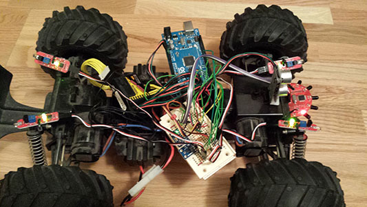 I've been working hard on a test board for the robot. I believe I have all of the sensors that I have received mounted on my bread board and everything fully wired together, except for the DIP switches. I hooked up most things with wire ties for temporary measure and they fit so well, I may just leave it that way or at least do something similar if I have to move them. I didn't attach the arduino or the breadboard, so they're currently just hanging there.
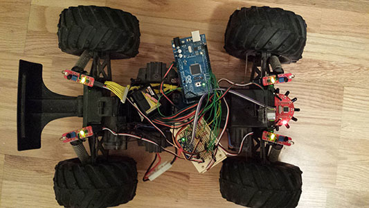 I'm going to continue working on getting all of the required sensors in place, defining standard connectors, and developing a master program while I wait for the parts I have on order to arrive. By having standard connectors for digital, analog, UART Serial, SPI, and I2C connections, I'll be able to plan for expansion and know I won't need to make a new board in the future. I also realized I'll have to get a mini drill press. I don't have access to one anymore and that's necessary to drill holes for a homemade circuit board.
I also am starting on a circuit board design. I downloaded Cadsoft Eagle and installed it as a free version since the limitations, at this point in time, shouldn't affect my design.
1/4/2014
So, I've been working on getting the sensors working on the arduino. I decided to start with my existing Accelerometer/Gyroscope chip (MPU-6050), since it is the predecessor to the MPU-9150 that I ordered a few days ago. I was able to get accurate readings off and even so far as to use the build in digital motion processor using sample code in the i2cdevlib library that can be downloaded here. As a bonus, this sensor also can sense temperature, which I'm pretty sure the one I ordered can do as well. Although I hooked up my magnetometer through its auxillary I2C connectors, I have yet to test it.
Next I hooked up my IR detection sensors, but I haven't tested those yet either. I created a simple circuit with a CdS cell (photocell) and a pulldown resistor and hooked that up to an analog port and that tested successful.
After that, I hooked up my IRDirection sensor. I found some code on the internet that wasn't quite working. After changing a couple things in the code, I got it working successfully. My idea was to use the photocell to detect the light level and if the conditions were right, it could make use of the IRDirection sensor to go towards light. The sensor is really more of a light detector that senses the IR in light and can tell which direction it is strongest.
Next, I need to test out the IR obstacle sensors, which should be really easy because they are just a digital on/off. Then I can work on getting the data for the compass and showing that. At that point, I believe I will have tested all of the sensors I have, including the ping sensor and RC Inputs from before. I should work on the outputs at that point. I obviously have the robot's servos and I wanted to use some LEDs as lights on the robot, since it is a vehicle and then the fun part is to try and combine the sensors to overcome various obstacles.
With planning for some future expansions,such as maybe a color sensor, GPS, possibly a camera, and additional servos or additional input sensors, I should be able to start working on a board design.
1/1/2014
Happy New Year!
I assembled the arduino shield kit yesterday. Then I started taking inventory of all the sensors I have and all the ones I plan on getting. I ordered the SD Card board with the built in converter. I also purchased a MPU-9150 based Accelerometer/Gyroscope/Compass chip. I decided on this chip rather than a separate magnetometer and Accelerometer/gyroscope for a couple of reasons. First, it takes up less room on the board. Less room means more compact electronics. Second, for compass readings, it can automatically take tilt into account to get accurate compass readings.
At this point, I'm figuring out all of the connection needs for inputs and outputs. Next I'll prototype a circuit out with some breadboard and then I can start working on an actual circuit board design.
12/29/2013
It's been a while. As a quick update, I ordered and received those additional parts, started a new job, and have moved across the country. Somebody at my work had done a presentation on RC stuff and I learned about some new stuff that was out there. It has been a few years since I originally looked up my information on Radio Control technology, so I did some more research and discovered something very important and a bit frustrating (in a good way). I found this article on Sparkfun that describes how to hook my RC receiver directly to my arduino and have access to all of the channels without taking up any more processing power than I was already using. So I unpacked my robot last night, took it apart and as a test tried hooking up my receiver to my arduino and seeing if it read the values. The test was successful.
What does this mean? It basically means I can take the PIC board out of the equation. It does mean I will need to use about 8 more pins on the arduino, but since I upgraded my arduino to an ATmega, this isn't really an issue. I will need to update my code, but it should make the code much simpler. At this point, I need to work on the shield redesign that will take these design changes into account. Before I do that, I will assemble the shield kit I bought (I may end up using this as my final board anyways) and start hooking up stuff to here. I need to work on finding my design notes regarding which pins I was planning on hooking the additional sensors to. If I can't find my notes, I may need to do some more research again.
5/7/2013
My parts arrived yesterday. I started cutting out some SIP connectors to connect the accelerometer, digital compass and directional IR sensor. The other IR sensors came with cables, so that was nice. Unfortunately, I ran a little short on connectors, but I was able to salvage a 4-pin connector from a computer speaker. I also found some ribbon cable that I'll use for these connectors. This means I need to add some pin headers for a 4-pin, 5-pin and 8-pin connector to the robot. That means I will probably have to remake my shield, which I thought I'd have to do anyhow so I can make use of additional pins on the bigger arduino. For testing purposes though, I will hook stuff up to a breadboard and connect that to the arduino using single wires. Once I get everything working, I'll redesign a shield. I'm sure I'll need to get more SIP connectors and pin headers to get that finished though. When you try desoldering used pin headers, it gets ugly. So, I'll be adding that to my shopping list. More work to do on it.
4/30/2013
According to package tracking, the sensors were just shipped yesterday. I'm still waiting for them to arrive. They're shipping overseas, so it may be another week or so.
4/25/2013
I haven't had any updates for a couple of weeks because I haven't done anything more yet. I ended up ordering some sensors for my robot. I ordered 4 IR sensors, a directional IR sensor module, a 3-axis accelerometer and a (digital compass). I just got notice that those shipped out today, so hopefully they will be here in the next week or so. I'll continue to post when there are any updates.
4/6/2013
For the most part, my program is fully operational now. I say for the most part because I still have a memory issue (probably a leak) that I need to hunt down. Looking at the stack trace, I suspect I may have overloaded the Debug Log TextView control. However, I now have it looping in a thread and updating the UI. I had to do a little function rewiting to make it so the communication didn't need to work as hard. I still have a few stability issues to fix. For instance, if the Android falls asleep while still connected, it needs to be rebooted. The program also seems to have trouble realizing it isn't connected anymore if you reset the Arduino without disconnecting first.
I want to optimize the code so that it's not so memory intensive, even if the issue is with the textview. I'll probably make it so that only certain types of messages get printed to the TextView and the rest go to the system log.
4/4/2013
I now have the code that shows the channels times. This is mostly working. Occasionally, a channel time is never requested, so I'm working that out. Anyway, I made quite a few changes to the overall program based on certain problems.
First of all, I was running into the problem of the program occasionally crashing as I worked on new features and as a result, I couldn't look at my log tab. So, I created a function that records it to the system log and outputs it to the log tab at the same time. After that, I was able to see a lot more of what was going on.
When I received data back from the arduino, I was using brackets to delimit the commands and I would receive the data in chunks and I would keep adding it to a buffer and process if it started and began with brackets. That worked fine for sending one command at a time, but when I started receiving multiple responses, I would get it chunked together with 2 or 3 responses sometimes. I added some code to check if the responses were chunked and would call the function to handle the responses and remove pending commands, which effectively turned it into a queue.
I noticed that when I rotated the android, it was losing all of the UI data. This seemed to only happen when going from portrait to landscape and vice versa. I decided to only allow portrait mode (and reverse portrait). I liked the layout for portrait much better than the landscape one I came up with, so I removed all of the landscape stuff. I have a little debugging to do and I need to add the ping sensor data as well as loop the program to get constant updates and this phase should be done.
I did have a good idea yesterday to add a section that I can use to reconfigure the way I want the robot to respond or behave as well as enabling and disabling features dynamically. This would be excellent for robotics competitions with certain rules and would take advantage of using a tablet, since it's so portable.
4/2/2013
I added the code that shows the features enabled and shows the lights for active RC channels. After a number of program crashes, I narrowed down the rogue code and had it check for bad values and display error messages to the log about why it was encountering those values. After that it started working. I optimized the code a bit by replacing parts with more efficient code as I figured out some better ways to do things. After getting that working, I tried making some channels inactive and a bug in the PIC program was immediately apparent. This is exactly why I'm developing my Android interface! It's a minor bug, but one I'll address as soon as I finish this stage of the android program.
Next I need to get the RC Channel Values for each of the active channels, set the value labels, and set the progress bars to show a visual of where the channels seems to fall. After that, I need it to display what the Ping Sensor is detecting. I also need to set the program to not read the RC Channels if that feature is set as disabled and the same for the Ping sensor. Then I need to clean up a few graphic details and it should be ready to run for now.
I also found a couple of interesting IR detection sensors. There's a basic one that I'm really looking getting about 4 of, since it looks like it does exactly what I want in an IR sensor for a great price. The more Complex IR Sensor looks interesting as well. It communicates with the Arduino (via Serial I think) and it can be used to tell where an object of interest is located. This one might be interesting to use with a camera that automatically point towards where it senses an object. So, that's where I am for tonight.
4/1/2013
 It's been a little over a week since my last update, but I've been working on on my robot. I actually made a lot of progress just tonight. Over the past week and a half I've completed several important items including coming up with a basic layout, which turned out pretty much what I sketched out on paper. The code for returning requested data is now complete on the Arduino side. I'm working on getting the Android interface to update based on the returned values.
I currently have the switches changing to the correct values, with which the command is issues upon connection establishment. I created tabs as I had planned and and finished laying out the interface tonight. I also created a landscape layout to accomodate turning the Android. I used Layout includes and created each section in separate files so I could easily rearrange things. I created a useful log tab which I can use to put any detailed debugging info on. The servos tab is for future use which I plan to use to control the servos with (if it's useful).
The next items are to finish are to get the rest of the data to display on the interface and then start a loop to get the android to send commands to request each piece of data so that the interface is constantly updating. At that point it will make sensor development much easier. For instance, I could create an IR sensor tab and display whatever test data I would like. This would allow me to get much more data than I could with a handful of LEDs or even an LCD display. I still need to mount the new arduino board (which is the board I've been using for development) onto the robot as well. It's currently sitting on top of the other board with a piece of paper acting as an insulator.
3/23/2013
I ended up attaching an external LED, which worked great. After doing lots of reading and internet searching, I've finally come up with a solution that has everything working nicely. I found a very nice Android Library called usb-serial-for-android. This was written with the main purpose of communicating with the android. Additionally, this library includes drivers for communicating with many Arduino devices including FTDI based arduinos like my Diecimila, which will save me a lot of time. Although the documentation is sparse, I was able take the example program and intergrate it into my own program. I did need to write a custom decoding function based on the HexDump.dumpHexString() function source code.
I also needed to update the Arduino test program slightly as well as my method of connecting. The current procedure is to plug the arduino into the program while it is running, give it permission to access the USB device, then push the reset button on the arduino. When that's done, a "connected" command is returned to the android, which then starts sending commands to gather information.
Additionally, I was having trouble with my program locking up the android whenever it went to sleep. As soon as I started unregistering my Broadcast Reciever in onPause() and reregistering it in onResume(), that seemed to solve the problem.
These were some tough obstacles to overcome, but with basic communications functioning, it's time to start integrating this into the main program and gathering relevant information, which I'll start on soon.
3/19/2013
Today I figured out how to update a text field from a thread by using the TextView's .post() method. I ended up creating a function that I can just call with the string and it tells the UI to update the text field. Anyhow, after I did that, I found a few errors in my code and fixed those. I looked into the USB specification documentation to figure out exactly what exactly the commands I found online to send to the arduino did. After some analysis, I found that it sets the Serial Line to 9600,1n8. However, my arduino was trying to talk at 57600, so I figured out the correct bytes to send it to request that speed. Now when I plug the arduino in, it tells me how many bytes were transmitted via bulkTransfer and the receive light on the arduino flashes.
I'm trying to turn on the built-in LED on the board, but for some reason it won't turn on when connected to the Android, even if all I have is code that tells it to turn on, so I need another way to test that data is being received. Most likely the arduino is correctly receiving the data at this point, but I don't like running blind with it when I'm doing things I've never done before. I'll probably try using other pins on the arduino and hooking up an external LED to see if that resolves the issue. Once I get the sending and receiving working on the Arduino Mega, I'll try getting it working on my diecimila. I'd like this project to work on all arduinos and I'm trying to write the code in such a way in case I decide to go with a different arduino in the future.
3/18/2013
I haven't had much opportunity to work on this over the weekend, although I did end up replacing the touchscreen glass that fits over the LCD on an android tablet that had cracked and that was very successful. I finally did some work on it today. I'm starting on working on the communications between the Arduino and the android. I set up the code to set up the serial connection and perform a bulk transfer. It's not quite working yet, but when I was trying to debug it by having the program print the status to a text field, it kept crashing until I remembered that you aren't supposed to access the UI from a separate thread. So the next step will be coming up with a way to have the UI automatically put the value of a variable in to the text field so I can indirectly write to it that way.
3/14/2013
So, for the past couple of days, I've been focusing on the Android code. There's a lot of learning to do, but as I gain a better understanding, I also understand new concepts that previously looked foreign to me.
Yesterday, I took some USB examples I found and figured how to integrate them into my code. It's not working yet (I had to comment out a bunch of the code), but it's closer. I ended up adding some code to request permission to use the device and that went ok.
Today, I ended up figuring out about interfaces and endpoints. You have devices, interfaces and endpoints that are in a tree hierarchy. By specifying Vendor ID and Product ID, you narrow down the specific device. From there, the device may have 1 or more interfaces. Each interface is like talking to a section of the board. For the Arduino Mega, I believe Interface 0 is to talk to the USB transfer chip and Interface 1 is to talk to the microcontroller itself, which is what I want.
From there, each interface has 1 or more endpoints. I've only seen 1-2, so I'm not sure if there are more. For my interfaces that have 2 endpoints, 1 is an input interface and the other is an output. I think you use these interfaces for sending and receiving data between the devices. Because the interfaces and endpoints are quite different in layout between the devices, I wrote some code that queries the arduino to get the information. I need to further write it to traverse the interfaces and endpoints and search for two endpoints that have a type of USB_ENDPOINT_XFER_BULK with one being USB_DIR_IN and the other being USB_DIR_OUT. That's about as far as I've researched. I still need to figure out how to actually use the endpoints to communicate with the Arduino, but I have some material to read to help me figure that out.
3/12/2013
I went ahead and put the new code on the old board, but it worked fine, so I knew it had to be something to do with the differences of the boards. I started a new Arduino project file and kept slowly adding things in with it working fine until I got to the SPI stuff. Looking closer at the Arduino documentation revealed that the boards did not use the same pins. However, the 6 pin ICSP headers had the SPI pins on them and were consistent between boards. I went ahead and made some modifications to my shield and wire harness so that it was able to plug into the ICSP header rather than be wired to the board. I went ahead and tested it and the SPI code was working again. Unfortunately, there are now additional things to plug in between the 2 arduino boards, so I will most likely redesign my shield eventually and have it plug directly into the ICSP header in the new design. I'll also be able to take advantage of all of the extra pins that way, but before I get that far, I'll build some more sensors. First though, I'm going to get the tablet working with the robot and go from there. At least this is forcing me to review all of my old code, which is very helpful.
3/11/2013
It's been a while, but I've been getting back into the robotics project again. There are a couple new things. First of all, I kind of broke the ICD2 board by plugging it into an incorrectly wired USB port. When trying to replace the USB chip, I lost some traces, so I may have to remake a board in order to get that reworking, but that's on hold for now.
The current project is connecting my Android tablet to the Arduino and using that for testing/debugging purposes. To do that, I'm learning Android programming. So far I've made a program that runs in host mode on the tablet and detects when the Arduino is plugged in and unplugged. Then I started working on the Arduino end. I'm starting work on code that communicates with the computer in serial mode over USB. That's coming along pretty good so far. I picked up an Arduino Mega 2560 R3 in order to upgrade the board for my robot to one with more connections for future expansion. I integrated the serial code into the main OS and programmed it onto the new board. By looking through the source code, I figured out where to correctly plug the wires. However, when I plugged in the new board, it didn't quite function correctly. I plugged my Arduino shield into the old board and it functioned correctly, so it's either the code or the new board. So I'll try reprogramming the old board and see what happens. After I get the Android tablet working with it, that should make testing this much easier.
10/27/2010
Well, I did get some more work done on the servo replacement board. However, due to too many components being required, I won't be able to make a board that fits in the miniature servo. However, I do have the option of taking the original board out of the robot and putting it back into the original servo and then putting the board I'm designing into the robot. I'm almost done with the servo board, but have been side-tracked lately with working on putting MacOS on my laptop.
Some good news however. I ordered an upgraded ATMEGA328 chip for the arduino and received it today, so now it has twice as much memory as before and I have an ATMEGA168 chip to use on some other project. I also ordered some replacement drill bits, so I should be able to make circuit boards once again (as soon as I pick them up). So, despite the 2 weeks of no updates, I have been making progress. Also, I should be able to take pictures with an old camera phone (I used it for some of the first robot pics). I can then take the SIM card out of the phone and grab any pictures off it, so hopefully pictures will be soon to come again.
10/11/2010
The last couple days I've been working on the servo replacement board. I've been using the new ICD for programming the chip and it's been working well. Unfortunately, with the PIC12F683 chip, using the ICD2 for debugging purposes requires a debug header, which is a small board that interfaces between the chip and the ICD. In order to get the PIC so small, they had to remove some functionality such as the debug circuitry and the header basically functions as the debug circuitry they removed from the chip. Additionally, with so few pins hooking up an LCD display is impractical, although I found circuit that turns a standard HD44780 LCD in to a serial LCD. However, it turns out I didn't need it since I was able to get each aspect of the chip working and tested through a bicolor LED. I was able to reuse the code I created for reading PPM signals in the chip, but due to the chip running at 8MHz rather than 32MHz, I had to set the timer prescaler to a quarter of the value to get the same numbers. At this point, I need to build a simple h-bridge (just enough to turn the motor a little), test out the functionality of the h-bridge, and assemble the pieces of code I have working and then it should be ready to go onto a circuit board. I've located the SMD components along with their datasheets that I need for an H-bridge (that's the only way I'll fit it into a micro servo), and board design will probably happen in parallel to finishing the test circuit.
10/8/2010
Well, I went ahead and swapped the 2 USB chips and to my surprise, both tested good. I now have a working and tested USB powered ICD2 clone on a circuit board. I figure the USB chip wasn't working because of a bad solder job and probably 2 important connections had a short in them. However, my recent SMT soldering skills have become considerably better and the new solder job looks and works excellent. I also went ahead and modified the board so it is using the MC1458 chip. Additionally, I disconnected the Vpp (Programming voltage) from one of the op-amp inputs and that helped increase the programming voltage another volt, so it's now around 11.1 volts which is enough. I think the minimum was around 10.2 volts and I didn't want to be so close to the lower limit. Unfortunately I probably won't be taking anymore pictures for a while. I had a little accident and spilled a drink on the camera, but I still do have plenty of unposted pictures. On the positive side, this new tool should make any PIC development much easier and faster.
10/5/2010
 I finally got the ICD working yesterday. I ended up attempting to see what the test pin was on the FT232BL and in the process of moving around parts, it suddenly started working. I'm not quite sure of what was wrong, but it was probably a part that had a short in it and wasn't making a connection even though it was plugged in correctly. Anyhow, after I did that it was recognized correctly as a device on the computer. I went ahead and downloaded the firmware into the device, but it wasn't passing the self tests. After careful examination, I found a resistor plugged into the wrong spot and fixed that and it passed the self test after that. I also had a problem with it telling me it wasn't detecting the correct device. I just needed to select the correct part in MPLAB and that was fixed. When attempting to program the connected chip, it wasn't being successful in programming that chip, so I decided the voltage for the MCLR pin was a little too low and replaced my LM324 (quad op amp) with a MC1458 (dual op amp) and it had gone up another volt. Apparently that was enough because it was successful after that. So now that I have a working model of an ICD, I'm attempting to get the board I made working. I'm double-checking all USB chip connections and everything is coming up good so far, but I'm starting to suspect the chip may be bad. So if I can't find anything after a thorough test, the next step will be to swap the chips and use the good chip on the circuit board and test the bad chip out in the working circuit. So that's my plans with that for today.
10/4/2010
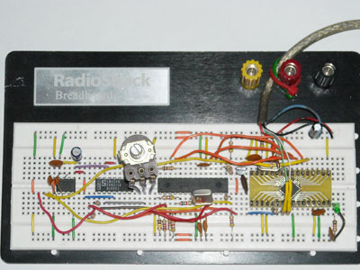 I've been taking a break from working on my robot and have been trying to get my ICD2 clone working. Back on 2008-6-3 I built a version that wouldn't even show as a device on the computer. After a little troubleshooting, I found a couple board design errors and fixed them so that I was generating 2 voltage levels now. However it still wasn't being detected, so I went ahead and built a version on breadboard. For the SMT chip, I went ahead and designed and built a breakout board, which seems to have come out good this time and I soldered a couple leads onto an SMT crystal. I ended up only using 2 components out of the original circuit and both of them were just socketed chips, so I was able to just pop them out of their sockets. Anyways, at this point it actually is coming up as a device on the computer, however it comes up as USB device not recognized. I've triple-checked the connections to the FTDI FT232BL chip and those all come up as good. Fortunately, the rest of the circuit is breadboarded, so changing connections here and there is quite easy and doesn't require a soldering iron. If I can get this tool working, it will help me a lot with any PIC development. If I am still unable to get the USB portion of this circuit working, I still have the option of using a MAX232 chip. I would just prefer USB since my laptop doesn't have any serial ports (my desktop computer does though).
9/29/2010
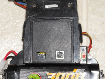 I finally went ahead and mounted the board with the USB port and DIP switches on it to the underside of the car beneath the battery flap to protect it. This took me a while since I had to carve exact holes for the parts and narrow the board and coverplate to get it to all fit. I also went ahead and shortened the yellow cable that goes between the bottom of the car and the board on top by clipping each wire, slipping some heatshrink tubing on, soldering the wires together and shrinking the tubing over the soldering job. Overall, I think the result looks pretty good.
9/28/2010
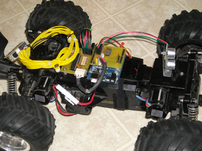 I've been quite busy the past couple days. I finished making the wiring harnesses, I ended up making another board that sits on top of the arduino, I had to do a little reshaping of the inside of the car, I mounted the Ping sensor, and I updated the code. The board that sits on the arduino is quite nice, since it organizes connections and distributes power very nicely. I can plug my servos and sensors directly into it that way. I also added a connector for an MMC card for the future with enough pins for SPI communication and one of the pins to notify the arduino if a card was inserted. That left 8 digital I/O pins (3 of them are currently being used by the servos and sensor) and 6 analog pins.
After I finished making the wiring harnesses, I realized that the top of the inside compartment wasn't fitting on so easily because I had used slightly heavier gauge wire than the servos had, so I ended up having to do a little reshaping to the plastic inside the compartment including removing the velco off the receiver in order to allow enough room. I also ended up widening the hole that the wires come out of and after that it ended up fitting well enough.
I didn't want the Ping sensor just sitting on the front, so I made a bracket out of a computer case blank and a couple of spacers out of some wall anchors which took me about 20 minutes and screwed it onto the front of the car. I ended up mounting it vertically, not only because it worked better that way, but the other way looked a lot like eyes which was kind of creepy.
With the new board I needed to switch one of the servos to a different pin, so I went ahead and changed the pin number in the code and uploaded it to the board and afterwards the ESC stopped responding to the remote. I guess I must have experimented with the code after the previous upload, so I went ahead and fixed the problem and actually got the code working exactly how I wanted it to. Also, The Arduino team had updated their software to version 0020 (I had 0018), which I downloaded and installed last night. However they had updated the SPI library, so I ended up making a number of code changes this morning to reflect the new library and tested it successfully.
I was looking up information about the accelerometer I had (the LIS3L06AL, which is now considered obsolete) to see what kind of interface it had. It looks like I had decided to go with analog outputs, so I should just be able to hook that up to the analog inputs and be good to go. All I have left to do really is mount the USB board on the underside, route the wiring harness, and drill a couple holes and everything should be done short of adding more sensors and updating the code, which is more of a longterm learning project anyhow.
And finally, I realized I still haven't named this robot yet, so I'm thinking about that. This is kind of a general purpose robotics platform that is fairly easy to change, test, and update for whichever task I want to accomplish, so I will probably be taking that into account when I figure out a name.
9/26/2010
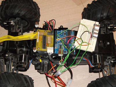 I went ahead and mounted both the Arduino and the new board I made onto the robot and created several wiring harnesses. I have 2 hooked up that go from the receiver to the PIC board and have another one going from the PIC board to the arduino for communication. After doing all that work, I finally tested it and it worked great on the first try. Today's work will be finishing up the rest of the wires going from the receiver to the PIC board and doing some work on mounting the USB/Switch board. This will include shortening a really long cable (the yellow one in the pictures) that I'm using which I pulled out of a computer monitor.
While I was going through my parts a couple days ago, I found 2 more IR TSOP1738s which would allow me to probably build a total of 4 IR sensors of standard design with what I have on hand. I also found an additional IR LED that I had bought. After I'm done with wiring and mounting completed items, my plan is to go back to the IR sensor and finish up the design with which I'll make 4 circuit boards for the IR sensors.
9/25/2010
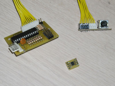 I've been working on modifications to my desk the last few days, but I decided to do some more work on the robot yesterday. I ended up making 3 boards complete with parts. I haven't tested the boards yet, which is on today's agenda. One board is the DIP switch and USB port board, which will be mounted on the underside of the car. Then there's the main PIC board, which will read the signals from the receiver and transmit the information to the arduino via SPI. The last board is for another robotics project I'm starting on the side.
I decided to remake the insides of the servo I took apart for this robot and got some PIC12F683 chips as SMT (so I could fit it in the servo). I'm trying to make a simple circuit that will read the PWM codes (that part should be easy) and adjust the motor with an H-Bridge circuit and read the position with the built-in 5k potentiometer using one of the chip's A/D converters. One reason I chose this chip (besides the small footprint) is that it can use an internal oscillator like the PIC18F2620 I'm using on the main board, so that's less components. I'm planning on doing the entire thing with SMT components and most likely a 2-sided circuit board so it takes up as little room as possible. I came up with a great way to do vias on 2 sided home made boards as a hobbiest, which is to basically take a wire and solder it on both sides of the board and trim it as flat as possible. The same thing can be done with soldering component leads on both sides for throughhole parts. Anyhow, the third board is just to allow me to use the SMT component on a breadboard for a circuit. I'm still unsure at this point how I'm going to program the chip, since putting in an ICSP header would make the circuit much larger, unless I can find a small 5-6 pin connector for that purpose. I still have a bunch of modifications to do to the car such as mounting the circuit boards, shortening the wiring harness between the boards and stuff like that.
9/21/2010
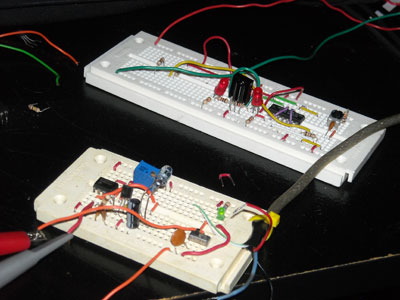 I continued working with the IR sensors. Apparently what I thought was working before was just noise in the line triggering the LEDs to light up. I wasn't sure what wasn't working, so I ended up building several 38kHz oscillators until I realized the problems was actually the IR receiver module. I was testing with a TSOP1838, which would detect a remote control fine because the signal from the remote is sent in pulses and that is the only way the TSOP1838 works. I plugged in a TSOP1738, which will detect a continuous stream just fine and as soon as I did that the sensor started working. I have 2 of each type of sensor, so with what I've figured out, I can only build 2 sensors at the most. One thing I'm also considering doing is some of my PIC16f84a chips and turning some plain old IR phototransistors (or are they photodiodes?) into something that will detect a 38kHz signal (similar to how I read the PWM) and set a pin as high (or low) to work like a TSOP1738. Additionally, I can also have it emit a signal on an IR LED and turn the entire thing into an IR sensor. The main downside is that each PIC16F84a requires a crystal, but I have enough crystals and chips to make 4 of those. It might also be possible to oscillate the oscillator for the TSOP1838 to work, but the effect would probably be a square wave on the receiving side, which I don't want.
9/19/2010
I've been working on some designs for an infrared sensor. I started by searching for designs already on the internet and have been working on getting something that works with parts I have on hand, and then I'll keep working the design down to use very few parts and as much as what I have on hand even if it means using just transistors and resistors if I have to. The idea will be to design a reusable IR sensor module with a small footprint, so I can mount them where I need them and use them in future robots if I want to. I currently have a basic circuit working, but the next step will be to reduce the number of expensive parts.
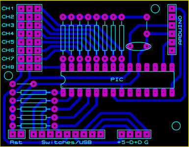 I went ahead and designed the main PIC board. It ended up considerably smaller than the arduino, which I wasn't expecting. I had measured the holes on the arduino in order to help with stacking, but due to the size difference, I was able to only use 2 holes. I put a placement for a third one so I could mount the boards side-by-side if I wanted. I added placement for 2 extra channel connections if I wanted to include this in the future without having to remake the board. I decided to not include the MMC card on the board since it would have dramatically increased the size. Since I'm not using it at the moment (due to not having the extra memory on the arduino yet to handle the code), I will create a separate board later. I'll probably just end up tying that into a connector board that will fit on top of the arduino. However, I still want to experiment with sensors before making a final design on the connector board.
For sensors, I'm thinking of using the Ping, IR sensors, an accelerometer, maybe a noise sensor, temperature sensor, light/dark sensor, and any other ones I want to try. My plan is to make a standard connector for sensors (probably 3 pin for +5v, Ground, and Signal) and have places for digital and analog signals on the connector board (which is why it would be called a connector board, though I may end up calling it a sensor board depending on what I come up with.
9/18/2010
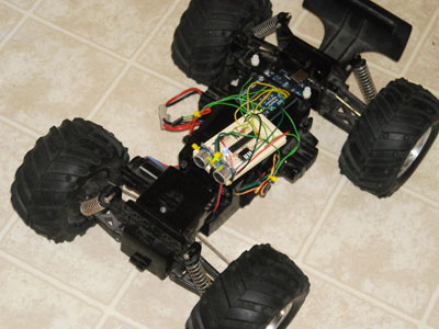 It works!!! After almost 3 years, I now have a working robotics platform. The first test I did was I just used the remote control as normal and it worked great on the first test, which was a great thrill. I set it to ignore the remote if the first DIP switch is on, so it can be used as just a robot without remote input. After that, I hooked up my Ping sensor and wrote a program for it to back up. I had to modify the code a little, but now it backs up if it senses an object within a half meter and stops when there is nothing else in front. The plan is to continue building and testing additional sensors and continue to evolve the main program for the robot with the additional sensors. Of course, I will continue finishing up with the circuit boards for the parts I've already built.
9/17/2010
In case you didn't notice, I found the camera. I took some photos this morning and spent some time updating my website so that I can add easy thumbnails (I don't have to have separate images, they are resized with code). I'm trying to add photos next to previous information that talked about a particular subject, like the sketch of the prototype I did and putting the parts on the small breadboard.
Well, I ended up solving the problem with the DIP switches not being read. Apparently for PORT A (and some of PORT B), you have to set the pins to digital through the ADCON registers. After that, it worked pretty good. I still need to get the servo code working, but there's lots of examples so that should be easy. Then I'll test it with remote control input, and then I'll try using the Ping ultrasonic sensor (there's code for that too) and write a small program for the car to back away if something is in front of it.
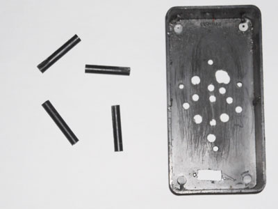 I was trying to figure out what would work best to mount the boards. I had some old gray plastic spaces, but only had 3 of those. I decided to take some posts out of an old RadioShack project box that I used for some kind of speaker thing when I was like 10. The next step with the posts will be to drill completely through with a 9/64" drill bit (to accomodate a 1/8" bolt) and then slice the tube into little spacers I can use. Another option would be to not drill it, leave the posts somewhere between 1/2" and 3/4" long and feed a screw in each end.
When it comes to making things, I tend to have a few rules I like to go by that really make things go smoothly:
- Start by making something that works and improve it after that.
- Wait until as long as possible before doing anything that would be difficult to undo.
- Make use of materials that you already have. Anything is up for grabs and sometimes a trash can will be a treasure trove of raw materials (just be sure to clean them first).
- The internet is full of ideas. If you don't know the answer, it's very likely somebody else will (and has probably asked it with a nice answer sitting next to it.)
- If you don't have the right tool for the job, you can often make it.
9/16/2010
 I wanted to upload some pictures of the progress so far, but when I searched for the camera I couldn't find it. Anyways, I went ahead and put the 18F2620 onto one of my small breadboards and added all the resistors necessary to run it. I also took the code and stripped it down to it's minimal function by removing LCD and LED test code, which brought it to around 750 bytes, which is quite small nowadays. I went ahead and tried it, but wasn't able to get any results with regards to SPI. I decided to separate my code and set it up for the 2 different chips, so I could take what was working and what I wanted and get it to a middle point. It turns out that on my small board I had accidentally tied MCLR to ground, which caused a constantly resetting chip. After swapping that around it started working fine.
Additionally, I kept having problems with my programmer. I noticed it worked fine on the 40-pin chips, but not 28-pin chips, so I figured it had something to do with the 40 to 28 pin adapter (which it did). I eventually narrowed it down to an intermittant short on the PDC pin (pin 27 on the 18f2620). I went ahead and resoldered it and it seems to be working much better.
I'm currently only having trouble with reading the DIP switch values via SPI. It should be fairly straight forward, but it might be something to do with reading a PORT value within an interrupt service routine. I'll start by trying to see if it's even reading the PORT value at all. If it is, I may have to do a little workaround by just reading the value within the main loop and storing it in a variable.
Adding commands into the PIC is actually pretty nice, because if I need to make any parameter changes in the future, all I would need to do is change it on the arduino. I also want to add some code to check if the values are within a certain range like 600-2400 before storing them into the array. By having a command for changing that range, all I would need to do is set it through the arduino.
So far, the project is coming along pretty nicely. I still need to come up with the PWM code on the arduino, which should be pretty easy. After that, I can mount the arduino and breadboard on the car and it can get it's first test. I have an ultrasonic sensor from Parallax that I will probably use as one of my first sensor tests. I still need to at least get the switch code and PWM code going and then I can do the first trial run. Hopefully I can find the camera by then so I can take some pictures.
9/15/2010
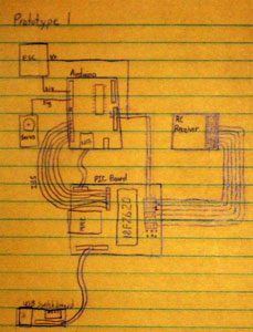 I went ahead and drew out a sketch of what I wanted to put onto the first prototype board. In this version, I will only be making 2 boards. One, which I already designed, will hold the USB port that will be extended from the Arduino for easy access and a set of 4 DIP switches. The second board will hold the PIC chip, pins for input from the receiver, and the MMC card. Originally, I was debating on whether to use the 28-pin PIC18F2620 or the 40-pin PIC18F4620, which would give me an additional 8-pin port, but upon seeing how little space I had to work with, I decided to go with the 18F2620, which is significantly smaller. At this point, I'm still making preparations for getting the first prototype up and running. At the very least, I should be able to put together a PIC board on breadboard and mount the arduino to get a pre-prototype in the next couple of days.
9/14/2010
I ended up looking at I2C another time, but didn't have any better luck. It just seems to be a protocol that the 2 types of chips aren't able to communicate with. I have been going over the possibility of using the ATmega chip I'll be replacing from the arduino and transferring my algorithms for reading timing over to it, so it would be able to communicate better with the arduino, but it probably won't happen.
I ended up making a change to the prescaler of the timer on the PIC chip. I changed it from 1:1 to 1:8 because after that change, when I converter the values to decimal, I ended up with numbers in the range of 1000-2000. Since that was exactly what I was looking for, I'm going to stick with that.
I ended up hooking up all 6 channels to the receiver and as I was testing, I noticed hitting the trainer switch (all lines went high) caused it to get stuck sometimes and not other times. I also noticed it worked similarly when I wire was pulled. I couldn't get anything to work that either stops this or exploits it yet, but I'll keep trying.
While I was looking through a bin of cables, I came across some 1-sided copper board, so that should save me some money and make this project go a bit smoother. I have a robot book I bought a couple years ago that I don't remember mentioning before called Intermediate Robot Building that I've been going through. It has information on building a number of sensors that should really help with my project. Additionally, it comes with a fairly complete design for another robot that would be fun to try and follow along in building. But anyhow, that should be a helpful read as I go through it.
9/12/2010
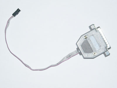 I pretty much worked on learning about the hardware for Arduinos and various AVR chips yesterday. I built a parallel port adapter, known as a dapa (Direct AVR Parallel Access) type that connects to the arduino. I had a little trouble at first since I didn't realize the USB cable needed to be plugged in too at first, in order to provide power. After that, it worked fine. Another option for programming the ATmega chips is to use the arduino itself to transfer the code from the computer to a chip sitting on a breadboard. I'm not certain if the Arduino software sets fuses and unlock bits (required for programming the bootloader), but I do have the commands to do it through the AVRdude software in case, so I should be able to upgrade to the ATmega328 when it comes, which I'm excited for.
9/11/2010
I finished getting the autodetect function running, so now the chip has the basic program on it that I set out to do a few years ago. For auto detecting, I just looped through 32 times while waiting for the timer to count from 0 to 0xb000 and looked for activity on any pin. If it saw some, it was set as active by just running activeChannels |= PORTD each time. I also took my timing code and made it a little cleaner and more efficient. The entire program is around 1.5KB, though I have 16KB of total space I can use on the chip.I have been kicking around the idea of using the same chip to send out PWM as well. A simple copy of PORTD to PORTB would probably suffice for normal operation. If I come up with code for sending out pulses (which should be pretty easy), I can do things like have a mode for just holding steering controls in whatever position I left them in. As far as I know, this is one of very few chips that can read 6 RC channels (possibly more) simultaneously, which is why I developed it. Perhaps, after some more work and additional refinement, it could be something to sell, since it's currently very specific to my setup.
I'm also thinking of looking into I2C. I learned a lot working with SPI. In order to get that working, I had to program the arduino and PIC with 2 mismatched configurations and now realize the same thing probably applies to I2C. My main disappointment with SPI is the fact that it takes up not just PORTC, but also uses a pin off the middle of PORTA, rendering it quite useless for many things.
I was looking into expanding the memory for my arduino as well. It appears just popping out the ATmega168 chip, popping in an ATmega328 chip, and programming a bootloader will double it's memory minus the size of the bootloader (about 2K). I'm looking into throwing together a simple AVR programmer as well, which will be required for uploading the bootloader. I placed a sample order for a couple of ATmega328's yesterday, so hopefully those will arrive in the next few days. I looked into using an MMC card with the arduino and found a library called SDFATlib, which would allow access to files that are PC readable. However, the library takes up a considerable amount of size, so the chip upgrade will pretty much be necessary to run that.
So I guess my next steps here are to create PWM generation code, look into building an ATmega Programmer, and take one last look at I2C.9/10/2010
Yesterday I got the code for transferring multibyte data via SPI working. I ended up using the first byte from the arduino to choose which channel I wanted to get data on, which stored the data on the PIC in a static variable, so I could get read multiple times without the number changing and then sending 0xff to get remaining bytes. It works quite well and I was considering setting it up so the first byte was a command, with subsequent bytes being data transferring back and forth. This would allow me to set the PIC up in different modes and allow it more capabilities than I had originally intended.
I also have a new algorithm for the timer to read multiple channels successfully. However, in it's current form it has some limits. First, I need to set which channels are active for it to work. Second, if there is no data being received from an active channel, the entire thing stops until it starts getting data from that channel. I'm trying to devise a way for it to automatically detect which channels are active upon initialization, but I haven't come up with anything reliable yet, so it has to be set manually. Additionally, the way the timing is working, it appears the first channel is taking just a little longer for timing, but it may just be in how I have the RC transmitter programmed. So my current task is to try and either detect the active channels automatically, or modify the timing algorithm to not require this. Another option would be to add the option to send commands via SPI, so the active channels could be set that way. At this point, I'm very close in getting a first prototype of the robot running.
9/9/2010
I got my timer code working nicely. I originally kept losing the the high byte of the timer because even though I bitshifted, my timer variable was only 8 bits, so when I shifted the bits over, they would just fall off the undersized variable. As soon as I started reading into 16-bit variables, the problem went away. When I generated my algorithm, I had assumed that the signals for all 6 channels occurred simultaneously. However, upon hooking up 2 channels of my oscilloscope together I discovered they actually occur sequentially, so as soon as one channel ends, the next one starts. An easy way to fix this is to use one channel's end time as the next one's start time. Now, if I have all 6 channels connected at once, this isn't a problem, but I want to be able to have channels missing and still have this work correctly. One way around it might be to have it detect active channels and check only those. It just gets a bit tough when dealing with microseconds and efficient code is extremely important. So the goal for today is to figure out an algorithm that addresses the new information and possibly to code it in.
I reattached the strut I had repaired yesterday and it seems to be holding up nicely. If it bends enough to need another repair, my next step will be to temper the pin so that it's much less bendable (more like a drillbit).
As far as figuring out the other boards and MMC, I've decided to put that on hold until after I get the timer code working. Also, since I've decided to store the values as 16-bit numbers, I will need to figure out a way to transfer that via SPI, since I've only tried sending 8-bit numbers. In the worst cast I could always send it as a high byte and low byte, but I'm pretty sure that's unnecessary.
9/8/2010
I started work on the timing coding. Unfortunately, at this point it's behaving a little erratically. I hooked my oscilloscope up and wasn't able to get any clear reading. So, I decided to try the receiver in the car itself and charged up the batteries overnight. This morning, I connected everything and when I tried to operate it, I had no response. I did notice the car twitched if I shut off the transmitter, so I was pretty sure it wasn't broken. After pulling out the manual, I went through the settings and found it was in QPCM (Quick Pulse Code Modulation) mode rather than PPM (Pulse Position Modulation) mode. After changing it, the receiver responded just fine. I hooked up my oscilloscope to the receiver after plugging it back into my circuit to visually see the waveform and I had been expecting it to be high at idle and going low for a period of time. However it was the opposite, so I'll need to adjust the code to my new findings.
Additionally, I noticed that one of the struts on my car had snapped in half. I was able to carefully drill a hole lengthwise through the plstic on both pieces and fashion a pin out of a large paperclip that held the piece together. I added some JB Weld onto it and am just waiting for a few days for it to dry completely before putting it back together.
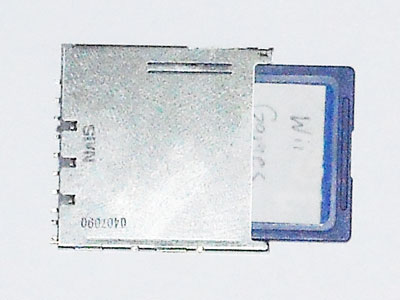 I made a diagram of all the pieces that will be going into the first build of the robot. I will need to make 2 or 3 circuit boards with 1-2 of them most likely being single-sided and the 3rd being double-sided. It will have a USB extension coming out of the arduino with a jack on the bottom of the car that will be protected by the battery covering so that I can update the arduino without disassembling the car. I will also be putting in a socket for an MMC card for future use, however I'm undecided about the MMC card being part of the PIC board or it being a separate board at this point. I will also have a board that will fit on top of the arduino and provide connectors to other the boards as well as places to plug in sensors. There will undoubtedly be some changes to the design as I learn more, but the design is definitely coming along nicely at this point.
9/7/2010
After a lot of fine tuning and tweaking, as of last night, I've finally been able to get the PIC and arduino to communicate without errors. I've noticed that occasionally one of the shift registers gets it's bits rotated on power-up, but a reset of the arduino seems to fix the problem. I'll still look into that so it can work reliably.
The next will be reading PWM values from the receiver. According to documentation and as I've seen on my oscilloscope, the times should vary between 1000-2000 microsecond pulses depending on the direction of the controls. My plan is to have a 16-bit timer constantly running from 0-65535 and looping back in order to have something to measure time. Also I will be having the PIC running in a loop and taking note of any changed states of the 6 lines it will be monitoring and calculating the length of the pulses. I'll then have it throw out any values out of the expected range. Once I get the measurements I'll use the number to calculate a value between 0 and 255 and store in on the PIC. When the arduino requests a particular channel's value, the idea is to just send the last stored value for that channel back to the arduino.
For testing purposes, I'm also swapping the 18f2620 for it's bigger brother, the 18f4620. It has an additional port (Port D) that I can use for PWM testing while still allowing the LCD screen to be connected. After I get everything working, my plan is to disconnect the LCD (and remove the code for it) and use port B for connecting to the receiver.
9/6/2010
I decided to give I2C a last final effort, which included tons of searching on the internet. The problem is that other than the start and stop bits, the interrupts are never triggered. I double-checked so many things and actually found a few things to fix, although it didn't really make any difference with the results.
So after reading about SPI since last night, I was able to figure out the code for the Arduino and get that programmed pretty easily as a master and set it up to send out data every half second. I did some reading about the PIC and got that set up so it initialized and would display some data on the LCD if it received any data. On the first attempt, I was able to start displaying information on the screen. It looks like I'm going to use SPI despite the additional wires/pins it uses because it works. After doing some more reading and fine tuning, the next step will be to get specific data flowing between the 2 and then I'll program the PIC to start reading and storing values from the PWM (remote control) receiver and storing it so that the arduino can just query the PIC chip any time it needs those values. After that, it'll be time to get to the fun part and actually creating the main program that will run my robot.
9/4/2010
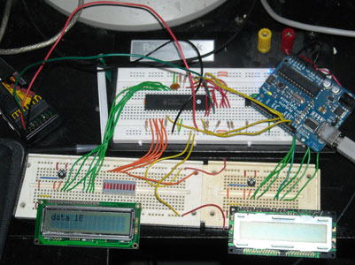 It's been a while since I updated. I ended up putting the logic analyzer onto a circuit board a while back and it works fine. I was still trying to get I2C working between my arduino and PIC chip, but still have been unsuccessful in even the simplest communication. I set up an LCD display that shows what the 1-byte values of up to 4 registers are. I also set up a second chip to attempt PIC to PIC communication via I2C and even hooked up another LCD display to that one, but after further investigation I'm going to look into trying SPI (Serial Peripheral Interface). SPI is apparently much better supported by PIC than I2C and there is an SPI library available for the arduino, which I've downloaded. So the next step is trying to get some communication going via either the PIC chips or the arduino and a PIC via SPI or even I2C if I can. One big advantage of using SPI however, is that it would allow me to make use of an SD Card in the system for tons of extra space as well as something I could easily reprogram without disassembling the circuit. However, I'm just going to start by taking 1 thing at a time for now.
6/1/2009
Well, I ended up building a logic analyzer this morning. I found an older laptop that I wasn't using for anything that had a parallel port and I built a simple analyzer out of a parallel cable. The design on the site called for a 74HC245 chip, which I didn't have, so I substituted it with some other chips based on how it was wired up. I ended up using 3 74LS04 Hex inverter chips and paired 2 inverters per input (8 inputs total) to create buffers, which is all the other chip was used for anyhow. However, I needed +5v and the parallel port was only providing about +3v, so I wired a PS/2 cable in to power the chips. I hooked it all up, tested and it worked (although it's still on breadboard for the time being). I still have much to learn about the I2C protocol, so that's what I'm working on doing now.
5/31/2009
Well, not much progress today for the most part. The 2 are communicating, but the results don't seem to be what I keep expecting. This morning, I originally thought one of the chips I had was bad, but it seems they got a little messed up when I tried writing to them without power plugged into my programmer. Doing an erase, a full read, and then a write (with power) seemed to fix it and once I figured that out, I haven't had any problems. This would be so much easier with a logic analyzer, but I don't have one, and I don't have the money to buy any parts to make one (at least not based on the designs I found on the internet). I could probably build one with what I have, but I think it would require a large amount of time spent on that and I'd rather not be side-tracked. I think I ended up spending a large portion of the day trying to get it working while using a reserved address, so I'm having to do a lot of testing all over again. I think overall, I just have a lot to learn about the I2C protocol. I think it will just be a matter of plugging away at this project until I figure out enough things to finally get it working. Fortunately, I tend to be more inventive with figuring out software, than I do hardware and finding bugs is one of my specialties; learning new things like this protocol is one of my other.
5/30/2009
It looks like I may have been a bit hasty. I decided to continue working on the project some more and here's what I've done in the last couple weeks and what my plans are at this point. I did end up bonding the bumper together, but when I was working on getting some metal for reinforcements fitted, I ended up snapping the bumper in half, so that's something I need to work on still. I continued working on fixing the breakout board for the dsPIC in case I could get that working. I came up with a wonderful technique (although very difficult still) of repairing the circuit board traces of such small width. I took some scrap pieces of wire that were left over from a null modem cable I made this past week (for a Sun Server I had aquired and finally got around to getting it up and running). From that wire, I used one filament of the stranded wire, which happened to be about the width of the trace (I had to do this under a magnifying glass), and soldered it along several of the traces. Unfortunately, about 25 of the traces were in need of repair and I still have about 5-10 more to do. I ended up giving up on that for now and went back to the arduino and PIC chip that I had settled on.
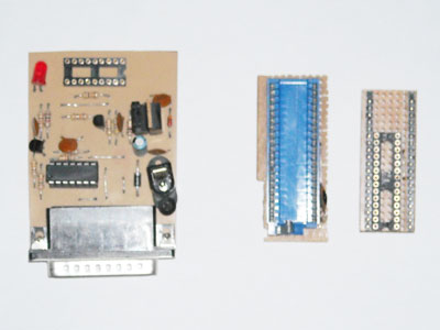 I'm currently in the middle of getting the 2 to talk via I2C. I've been having to do a lot of reading on the implementation for both circuits (the arduino is much simpler). With the PIC chip, when I was trying to write the program onto it, I started having difficulties with intermittant errors. Keep in mind that I had a breadboard with wires plugged from various pins on the chip to the socket in the programmer since it was originally made for 18-pin chips and I only had a 40-pin adapter. I discovered that if I plugged the wires in via the 40 pin adapter, it worked perfectly since it had a couple resistors and capacitors on it (which I can't remember is hooked up to what). Because of the inconvenience of the wires, I went ahead and built a 28 pin to 40 pin adapter that attached right on top of the other adapter since the pinouts for the 28-pin chip were almost exactly the same as the 40-pin chip. So, this is where I leave off tonight. Hopefully I can finally get I2C communications working tomorrow.
5/7/2009
I've put the work on hold for the most part at this point. I'm currently working on repairing the body of the car from the crash. Currently the front bumper is mostly intact using JB Weld to hold it together. After that, I plan on reinforcing it with metal so that it can withstand an impact again without crumpling. As for the electronics, I'm holding off on working on that for now while I get some other things done in my life.
10/14/2008
I changed the code so that it blinked a bicolor LED between green and red. It was having trouble and operating erratically. First I tried programming a second chip with no success, and then I ended up mounting all the components on a different breadboard. They seemed to work much more consistently on the new board. I'm now at a point where I'm doing more reading so I can start making use of the timer. Once I get that figured out, I'll work on getting 1 channel read and change the light between red, green, or both depending on the position of the control. After that, getting multiple channels working should be much easier.
10/10/2008
After doing some reading, it sounds like I2C will fit the bill after all. Hopefully I'll be able to make some more progress on this over the upcoming weekend.
10/8/2008
I made some progress tonight. I've been doing a bunch of research on various settings for the PIC18 series chips such as what the various fuses are and how to get it to run with the internal oscillator and use PLL (phase locked loop) to multiply the clockspeed by 4 to get a total of 32MHz. I had thrown together some code last week and uploaded it to the chip, but when I tested it, the LED didn't seem to blink. When I tried the program in a SPICE simulator, it seemed to run ok, so I wasn't sure what was wrong. I fixed my power supply, from which the voltage regulator had been resoldered numerous times had finally detached for the last time, by simply replacing it and wire-tying it to the board better. I hooked up the circuit and still it didn't blink. I couldn't locate my logic probe to test it, so I decided to try hooking it up to my oscilloscope. I was pleasantly surprised to see a square-wave pattern on the screen. What had happened was when I threw the test program together, I made a delay routine that just simply ran from 1 to 10000, which was simply too fast to visibly show up on the LED. With a bunch of testing and using the "stopwatch" portion of MPLAB, I was finally able to make a fairly accurate delay routine, which now works. I'm working on making the pseudocode (which is nothing more than a step by step description in english about how the program runs) for a program that will decode the PPM signals from the receiver and somehow transmit them back to the arduino (either via I2C, SPI or possibly analog output). I just love the irony of having a project that uses a PIC chip and an Atmel chip (2 major competitors) together.
9/18/2008
Last night I found a copy of the C18 compiler I had downloaded, copied and pasted a sample program into mplab and compiled it successfully. After that, I uploaded it to the chip successfully, erased my buffer, and read it back from the chip successfully, so my adhoc adaptor is working fine. Just FYI, my adaptor is just a breadboard with wires going to my programmer on corresponding pins for Vcc, Vss, MCLR, PGD, PGC, and PGM. At least it gets the job done. The next step is to get a program I had written for the PIC16F84a ported to the new chip and updated so it can be read via I2C. Once that's done, I'll probably make a custom circuit board that allows me to just plug in jumper wires from the receiver to the chip and have another set of jumper pins to communicate with the arduino via I2C. After that, writing a control program for the arduino should be quite easy assuming everything works as planned. I'm not sure if I already mentioned this, but there were 2 main reasons I am using a separate chip to read the pwm signals:
- It can be processor intensive to read the data and I'd rather have a dedicated processor for it.
- The arduino has a limited memory and I didn't want to waste it on code to read the PWM.
9/17/2008
Ok, it's been a while. I've been doing things like being in a musical, playing World of Warcraft, and learning the violin that have been taking up much of my time. However, I've made some progress on my robot. First of all, I've decided to go with an Arduino Diecimila board for the main controlling board. I had attempted to create a breakout board for the dsPIC processor, but my boardmaking skills just don't seem to be good enough. Sure I could order custom boards, but that gets expensive. Anyways, the arduino was only about $40 after shipping and everything. I chose this because it's a popular platform with a lot of code available for it and there's nothing to build for the main unit. I also purchased an oscilloscope, so that should help me with reading signals.
I've been playing around with how to get everything set up and I did lose a bunch of my diagrams, but I do have a lot of stuff in my head still. My current decision is to use the Arduino as the main board and for reading the PWM signals from the RC control, I'm going to use a PIC18LF2620 chip with some custom code and will communicate the values to the arduino via I2C. This is a 28 pin chip, so it's relatively small and I already have it. Also, it's in a DIP package, so it's easy to prototype with breadboard. My main challenge will be throwing together an adhoc adaptor to my programmer since it only does 18 and 40 pin chips, but I don't think that should be too difficult. I'll post further if I make any additional progress. The next step is to get the PIC chip working.
Ok, I put together an adhoc adaptor for the PIC chip on a breadboard with wires and tested an initialization and that seemed to work. The next step is to write a simple test program and see if I can write it to the chip successfully. I need to download and install the Microchip C18 compiler to do that and I'll probably take care of that tomorrow.
6/9/2008
I didn't do too much this weekend. I ended up putting the shell on and raced the car around again with my boyfriend. I also drew up a circuitboard design for the breakout board. So the next step is creating and assembling the circuitboard. Then once that's tested, I can figure out how I'm going to go about with programming it for the time being. I'm hoping I can just connect it to my existing programmer by building some kind of interface. After that I can start breadboarding out the actual circuitry. I also need to find a high-level block diagram I drew up for how the circuit will interact, although I'm pretty sure I could figure it out again if I had to.
6/6/2008
I went ahead and bought the remainder of the parts although I ended up needing to stop at 2 Radioshacks to get everything. I went ahead and put together some wiring adapters and finished hooking everything up. I recalibrated the steering and had to reverse the direction of the ESC through the remote, although I could have simply switched the colored wires. I used velcro to hold the battery cover in place and after putting the cover over the electronics and securing the extra antenna wire, it was ready to go. So I went ahead and took it outside to get an idea of it's capabilities. It raced just fine and was able to go very far. In fact, I was only limited by how far I could see the car. I think it went around 10-15 MPH by comparing it to other (real) cars going through the parking lot. Unfortunately about a minute or two into starting racing I crashed into a pole and snapped the front bumper into 3 pieces, which is mostly cosmetic anyways. I was able to race it up curbs, on grass and accidentally went through a puddle a time or 2. The only thing that stopped it was if it crashed into some bushes, which caused the wheels to become jammed in the branches from the inertia. All in all I'm pretty happy with the car. I think it's probably the best one I've ever had. The next steps are going to be fixing the bumper and starting on the main robotics board, which will probably start with me making a breakout board for the processor, which hopefully shouldn't be too challenging. I also took a bunch of pictures available for viewing below.
View Robot Photos
6/5/2008
Last night, I went ahead and bought an ESC and a new battery. The ESC was quite a bit cheaper than I was expecting at only $30. I got a new battery because it was a NiMH (Nickel-metal Hydrite) and had a much bigger capacity 3000mAh (milliAmp Hours) over my old NiCd battery with only 1200mAh although they had batteries with capacities up to 5000mAh. I also discovered a hidden battery compartment for the old circuitry that could hold 4 AA batteries, although I don't currently need it. I may make use of that if I feel it could be beneficial to any additional circuitry. The ESC was able to provide power to the receiver as well as the servo, so that was a definite bonus since I won't need the AA battery pack that came with the receiver. Also, it looks like the ESC has very low resistance and a small footprint, so I see little benefit in building one myself.
I went ahead and soldered 2 wires together inside and insulated it with heat shrink tubing that I had bought and then secured the receiver inside with some velcro. Then I desoldered the switch from the ESC and soldered a bigger one that came with the car so it would fit inside the switch compartment. Then I straightened out a bend in one of the front tie rods (probably from the previous owner) and reattached the front bumper. At this point, I need to buy some bullet connectors, heavier gauge wire and some method of securing the battery compartment door since the tabs have been worn down over time. I figure I can use velcro for that. I'll head over to Radioshack later today to get those items (they should have all of those things) and then I can finish assembling the car tonight and recalibrate the steering so that I can at least get it running as a basic RC vehicle, which is excellent for the summertime.
I also was looking into the costs for a real ICD and what a development board would cost and the prices seem more reasonable to me--especially on ebay. I may get those eventually if I can't get my ICD clone working.
6/4/2008
Ok, here's what I did last night. I started trying to design the new circuit and realized I would need some kind of transistors to drive the motors, so I decided to go a different, but easier route. I checked the value of the potentiometer inside of the pseudoservo and it tested at 5K ohms. Then I took apart my existing servo, and did a little testing. Inside the potentiometer was reading at 2.6K ohms, but I figured it might have another resistor in parallel, which would drop the resistance, so I desoldered it from the circuit board (after carefully diagramming it) and retested the potentiometer. It tested at 5K ohms this time. So I went ahead and put the circuitry from my existing servo inside of the pseudo servo, so now it's a real servo. I reassembled the car and tested and it worked although I do need to recalibrate the remote for the new mechanics, but this should be a very good solution. I may build that circuit for my old servo in the future anyways because it would be a neat circuit to have available.
The car I got is a Nikko Super Megatron which was manufactured under a number of other models as well. One of them was manufactured for Radioshack as the Desert Viper (I looked at a parts diagram to confirm this). I remember that particular car from when I worked there 12 years ago and it was their most expensive car and if I remember correctly, it went for about $225 at the time.
One of the main reasons I liked going with this new chassis is that it held a 7.2V batter as opposed to the 9.6V one I had in the truck. Most of the commercially available ESCs (Electronic Speed Controllers) would only go up to 7.2V, so this gives me a much wider variety of to choose from. The next things I am going to try and get are a commercial ESC and a new battery (the one I have is probably at least 15 years old and I haven't used it for that long either). Then again, I successfully used another 9.6V battery that was about just as old, but it doesn't hurt to have 2 batteries. This should give me enough parts to get a basic RC car up and running.
The next step would be to start making logic boards for the brain of the robot. I have been toying around with the idea of just buying a commercially available board with a chip of my choice as well as a bunch of support circuitry. That way I could just take care of the programming, which is the portion I am looking forward to the most (although I do love the challenge of getting things working mechanically). However, if I do end up going with my own design, I think I will start by creating a breakout board for the processor (a circuit board to which an SMT chip is soldered so that wires can be connected to each separate pin of the chip). That way I can just hook it up to a bread board and develop a much better understanding of how it need to be hooked up as well as to be programmed. In fact, I could most likely just hook up the processor on the breakout board directly to my existing programmer. I still don't feel like mucking with an ESC at the moment, but if I feel I could build a more efficient one, I may go that route after getting the initial car running.
6/3/2008
It's been a while since I updated this page. Since my last entry, I made many design changes. First of all, I decided to go with a dsPIC33F device that is specifically designed for motor control. It has many nice features that would make future expansion of the robot very simple. However, in order to use it, I need to have an ICD (In-Circuit Debugger) to program it since making some kind of adapter for my programmer would be impractical and the ICD allows debugging straight from the software, which is very nice. I went ahead and built a USB version of an ICD clone, but when I attempted to plug it into my computer, the lights lit up, but no new device was detected. I compared my circuitboard to the original schematic and found a couple design bugs, which I fixed, but it's still not working at this point. I wonder if I may have fried the USB chip when removing it. I do have another one and I probably should have tried breadboarding this before making it, but oh well. That portion is on hold for now.
Recently this past weekend, I had stopped by goodwill and found a Nikko 4WD car (I can't remember the model) that came without a remote or battery for only $6.99, so I bought it. I am now going to use this for the chassis. It's much bigger than my truck and looks more proportionate to my remote control size. The motor that controls the steering is basically a pseudo servo and has a potentiometer and a motor inside with some gears. I am working on designing a simple circuit that will read the PWM signal and control the position of the motor based on it's value. For that I'm going to use a PICF628A which has all of the basics I need. I should be able to get this circuit working in the next few days, which is extremely simple. I have more to update, but I need to get going.
10/22/2007
Ok, so here's what I did this past weekend. I started by working on the steering. To start with, when I loosely put the old parts in, I realized there was a new problem. The servo has a larger turn radius than the old motor. So, I needed to redesign how the steering worked somewhat. I decided to go with a steering method similar to what was originally in the car. The first step was to figure out how long to make a lever to make use of the turn radius of the servo in order to get the full turn radius of the wheels. I did a measurement or how far a know lever turned on the motor and using tangents, I calculated the angle the servo turned (approximately 120°) as well as how long of a lever I would need. Then I redesigned the bracket in my head and fabricated it out of brass using a variety of tools. I also designed and created a new linkage, while making use of the existing tie rods for the wheels, and assembled the whole thing. I gave it a test and it worked pretty well, but the only thing I'm not too happy about is that it has a bit more play than I would have liked, since I didn't have a good way of making it easy to disassemble while securing the tie rod to bracket linkage from rotating. I may go back at this and build an improved version with better leverage that addresses the looseness problem. Also, the weld stuff does hold to metal quite good, so I'll probably make better use of that as well. It's good enough for now though and the steering does actually work for all practical purposes. I took some pictures of the linkage, but have yet to upload them.
The next thing I tackled was seeing if the rear drive motor could be upgraded. I bought a larger DC motor at Radio Shack and decided to test it's RPM on the same load and voltage as the old motor before doing a replacement. I took another motor to use as a generator and connected a gear to it. Next, I hooked up my multimeter to the generator motor to measure the voltage output. Then taking each of the motors and connecting the same gear to them, I tested how much voltage each generated when turning the generator. Surprisingly, the original motor produced more power, so I decided not to make any modifications to the rear of the truck. I reassembled it and used some epoxy to make a couple repairs while doing so, since some plastic parts that had snapped off in some crashes which probably occured when one of my kids was driving it.
Next I started looking at electronic speed controllers designs again. My biggest worry was how I was going to read all the radio inputs into the microprocessor. Most of the designs which used a pic chip read no more than 2 channels for reading the PPM (Pulse Position Modulation) value to determine what positions the controls were in. Since I wanted to make use of the 6 channel RC Transmitter/Reciever that I had, I was looking at various ways to tackle this. One that I had been considering was assigning the task of reading the PWM (Pulse Width Modulation) signal with separate pic16F84a chips and communicating information back to the main pic16f877a processor, but I wanted to see if I could find a simpler solution. After doing some research, I'm thinking of making use of an octal latch chip (such as the 74LS373) to latch in the values of all 6 channels and loop through them, which will allow me to make calculations to determine the pulse widths on all channels without channel values changing during those calculations. Then I could make use of just the pic16F877a without complicating the design too much with a bunch of other unneccesary extra parts. That will also keep my costs down and it's much easier to make software tweaks using 1 microprocessor than multiple microprocessors.
Since I have somewhat of a good idea about what I'll be doing with hardware, I'll be writing the initial software soon. For the test circuit, I'll probably do something low power like rapidly blinking an LED or 2 to give it the illusion of changing brightness as the controls move. Either that or I may just output something on an LCD display, for which I wrote some nice code to interface it about a week and a half ago.
10/19/2007
Most of my work up to this point has been research, collecting tools, and getting some code working for the microprocessor. I also took the original 27MHz circuit board and diagrammed a schematic out. A few days ago I started implementing the mechanical changes and upgrades to the truck. I ordered some books on robotics to help out with some of the details as well as to provide an easy reference if I need it. I've been able to do more work on it lately since I was off work to recover from having gallbladder surgery.
So far I have taken the truck apart down to small pieces and started the replacement of the front steering. It was using a motor with gears and a small circuit board inside that provided feedback to the controlling circuit so the motor would stop when the wheels were turned. I took that apart and removed all the gears and motor and used a Dremel tool, a drill, and some files to be able to fit the servo inside the old motor casing. My challenge was to place the servo inside the truck in such a way that it would require no modification to the servo itself if I ever needed to replace it. After carving it up, I used electrical tape to secure the servo from shifting around inside. Then I took one of the metal gear posts from the original parts I removed from inside the casing and secured the post in a location so the new unit would still fit into the truck in the same way the original motor component did. So that fits into the car well and lines up just right.
Now I am working on designing and creating a bracket so that I can attach the old linkage that controls the wheels to the servo without modifying the servo at all. I have a general design in my head at the moment, but I am testing some of that liquid welding stuff between the 2 different metals I am going to use. I applied it this morning and it's currently drying. If all goes well, then making the bracket will be simplified. Otherwise, I'll just come up with an alternate design. So the plan is to get the steering functional this weekend. I'll also be working on a design for the speed controller and I may order some parts to be able to create that. I've found a couple of good designs already, so I'll most likely be using those as a base. I also found a good design for an H-bridge online, but I'll need to look that up again since I forgot where it was (although I think I remember). Hopefully I'll be able to at least get the truck running as an RC truck with digital proportional steering in the next few weeks. Adding sensors (such as an IR sensor) shouldn't really be all that difficult and there's supposedly a good design in one of the books I bought as well as some designs that I found online.
10/18/2007
I have been working on converting a radio control truck into a robotic truck. It's not going to be an android (human-like) like many people associate with the word "robot", but rather I'm implementing an electronic "brain" along with some sensors and other features. I may do something like giving it the ability to store "tricks" into it's memory, but that can come later. This webpage is to document my progress as well as provide updates for anybody interested.
The plan is to use a pic16F877a microprocessor for the central control and add additional components as needed. One of the nice features of these chips is they can communicate with other PIC chips, so I can expand if necessary. I already had a programmer (a device for writing programs onto the chip) for a pic16F84a, which is an 18-pin device, but I designed and built an adapter for the pic16F877a chip, which has 40 pins, and it works wonderfully.
My remote control truck is one I got quite a few years ago at Wal-mart, with controls that are either on or off. This means it can be stopped, full-speed forward, or full-speed backward, but nothing in between. It's the same thing with the steering: left, right, or straight.
My first task is to take my remote control truck and replace all components inside to give it digital proportional control, which means it has variable speeds and steering. I bought a radio control transmitter and receiver pair designed for remote control aircraft since it has quite a few additional controls besides steering and throttle so that I can control any additional features I want to implement. Plus the new frequency will allow the truck to go much further than the cheapo circuit board it came with. I also bought a servo for steering and I'll build an electronic speed controller for the throttle. Building it myself will allow me to make better use of the main processor for speed and direction control. I'm also planning on using the landing gear switch to control headlights and taillights (which I am adding to the truck along with reverse lights). Most of the lights will be automatically controlled by the microprocessor using the sensors and current remote control input.